TA202
34 www.baumer.com
The electronic outputs are not short-circuit proof!
➜ Assign terminals 10, 11 and 12, 13 accordingly.
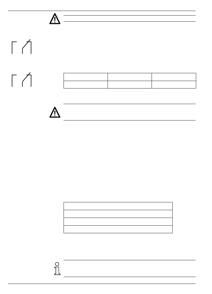
22 21 20
Limit value 1
25 24 23
Limit value 2
3.3 Assigning the signal outputs (relay contacts) option
Terminals 20, 21 and 22 as well as 23, 24 and 25 are potential-
free changeover contacts. The signal outputs can be assigned in
accordance with the terminal diagram on the left. The limit values
are assigned in lines 33 and 34 of the program.
Max. switch. output Max. switch. voltage Max. switch. current
150 VA/30 W 250 V 1 A
The user is responsible for ensuring that a switching load of 8 A/
150 VA (W) is not exceeded in the event of a fault.
Internal spark suppression by means of two zinc oxide varistors (275 V)
➜ Assign terminals 20, 21 as well as 23, 24 and 25 accordingly.
3.4 Assigning the signal inputs
Terminals 6 to 9 are signal inputs. Terminals 6 (F1/A) and 7 (F1/B) are
inputs for the tachometer display F1. The type of signal and signal lo-
gic are determined in lines 23 and 24 of the program.
Terminal 8 (F2/start) serves
- as a signal input for tachometer display F2,
- or as a start input for time measurement depending on the setting
in line 21 of the program.
Terminal 9 (stop) is used as a stop input in the case of time measure-
ments.
Input resistance approx. 3 kOhm
Max. input level ±40 VAC
Max. frequency F1 10 kHz
Max. frequency F2 40 kHz / 25 Hz
➜ Assign terminals 6 to 9 accordingly.
3.5 Connecting the sensor supply
Connect the sensor supply at terminals 4 and 5. However, do not
use the sensor supply to supply unearthed inductances or capacita-
tive loads.