TA202
www.baumer.com
33
For protection against shock hazards as specified in EN 61010, stran-
ded conductors may only be connected using wire end ferrules with
insulating caps. Terminals which are not assigned in the factory must
not be otherwise assigned by the user. We recommend shielding all
sensor connecting leads and earthing the shield at one end. Earthing
at both ends is recommend to avoid RF interference or if equipo-
tential bonding conductors are installed over long distances. Sensor
connecting leads should not be laid in the same trunking as the
mains power supply cable and output contact leads.
3.1 Connecting the supply voltage
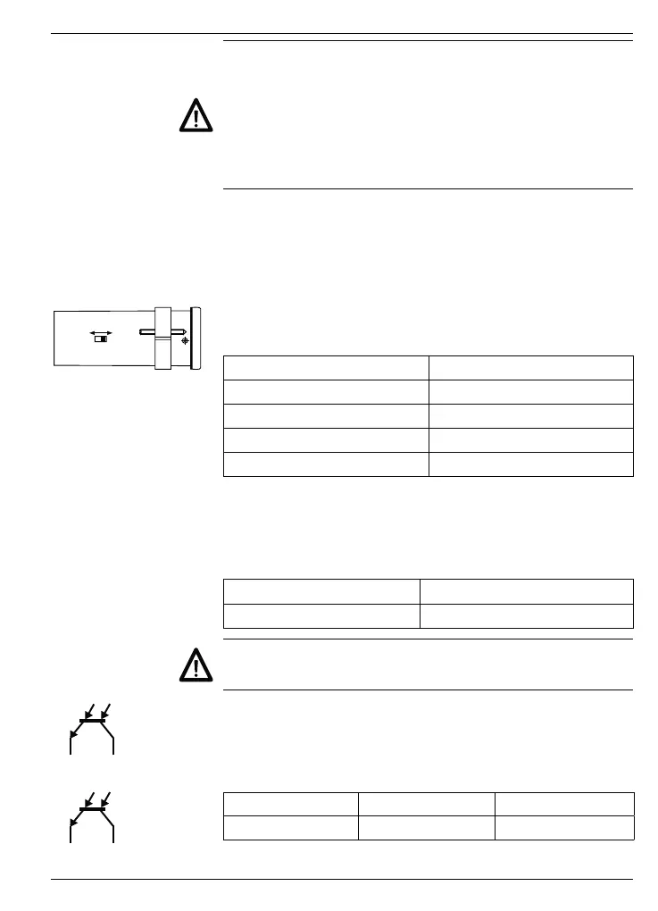
AC voltage It is possible to switch between two different alternating voltage
ratings as required using the voltage changeover switch accessible
from the side of the device. The higher of the two alternating voltage
ratings (48 V or 230 V) is set in the factory.
115 VAC
(24 VAC)
230 VAC
(48 VAC)
➜ Set the required alternating voltage at the voltage selector switch.
➜ Connect alternating voltage to terminals 2 and 3 in accordance
with the terminal diagram of the device.
Supply voltage Recommended external fusing
24 VAC ±10 %, 50/60 Hz T 400 mA
48 VAC ±10 %, 50/60 Hz T 400 mA
115 VAC ±10 %, 50/60 Hz T 100 mA
230 VAC ±10 %, 50/60 Hz T 100 mA
AC voltage Connect an interference-free supply voltage, i.e. do not use the
supply voltage for the parallel connection of drive systems, contac-
tors, solenoid valves etc.
➜ Connect direct voltage in accordance with the terminal diagram
of the device.
Voltage supply Recommended external fusing
24 VDC ±10 %, max. 5 % RW T 500 mA
Fire protection: Operate the device using the recommended external
fusing indicated in the terminal diagram. According to EN 61010, in
case of a fault 8 A / 150 VA (W) must never be exceeded.
11 10
Limit value 1
13 12
Limit value 2
3.2 Assigning the electronic outputs
The electronic outputs (terminals 10, 11 and 12, 13) are optocoupler
outputs with separate assignment of the respective collector and
emitter. Limit values are assigned in lines 33 and 34 of the program.
Max. switch. voltage Max. switch. current Max. residual voltage
+40 V 15 mA <1 V