TAM 00682 20
DSC 045-100 07 / 2012
Three-phase synchronous motor English
8 Annex 1: pole assignment (main connection and control port)
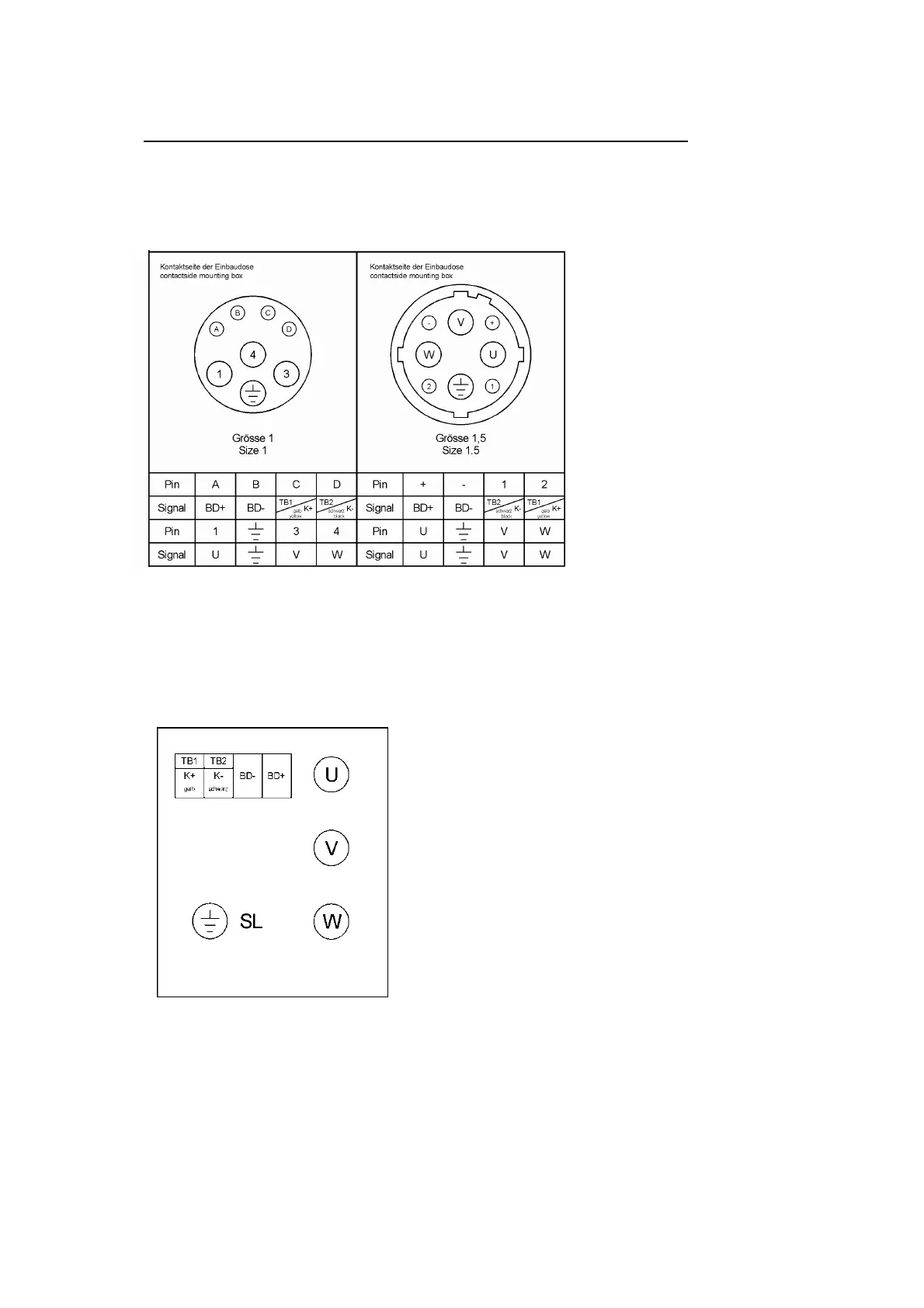
8.1 Main connection via plug
The standstill current I
0
of the motor determines the connector size of the built-in box.
Size 1: I
0
to 20 A; Size 1.5: I
0
to 36 A
Figure 2: Main connection with thermal sensor and brake
Note: If the thermal sensor is routed via the encoder channel, signals K+ and K- are
omitted from the wiring diagrams above.
8.2 Main connection via the terminal box (Standard design acc. to catalogue)
Use during standstill current I
0
> 36 A.
Figure 3: pole assignment with thermal sensor and brake
Table 4 shows the cable leads of the terminal boxes and the main connector pin assignment
together with the permissible torque specification.
On the connections for the cable leads we recommend the use of EMC connectors.