TAM 00682 22
DSC 045-100 07 / 2012
Three-phase synchronous motor English
8.4 Main and control connection via combination-mounting-box (customer
specific design)
This combination- mounting-box is generally mounted on the end plate on NDE-side. The box is
90 °angulated and contrary to the standard design of the motors not turnable.
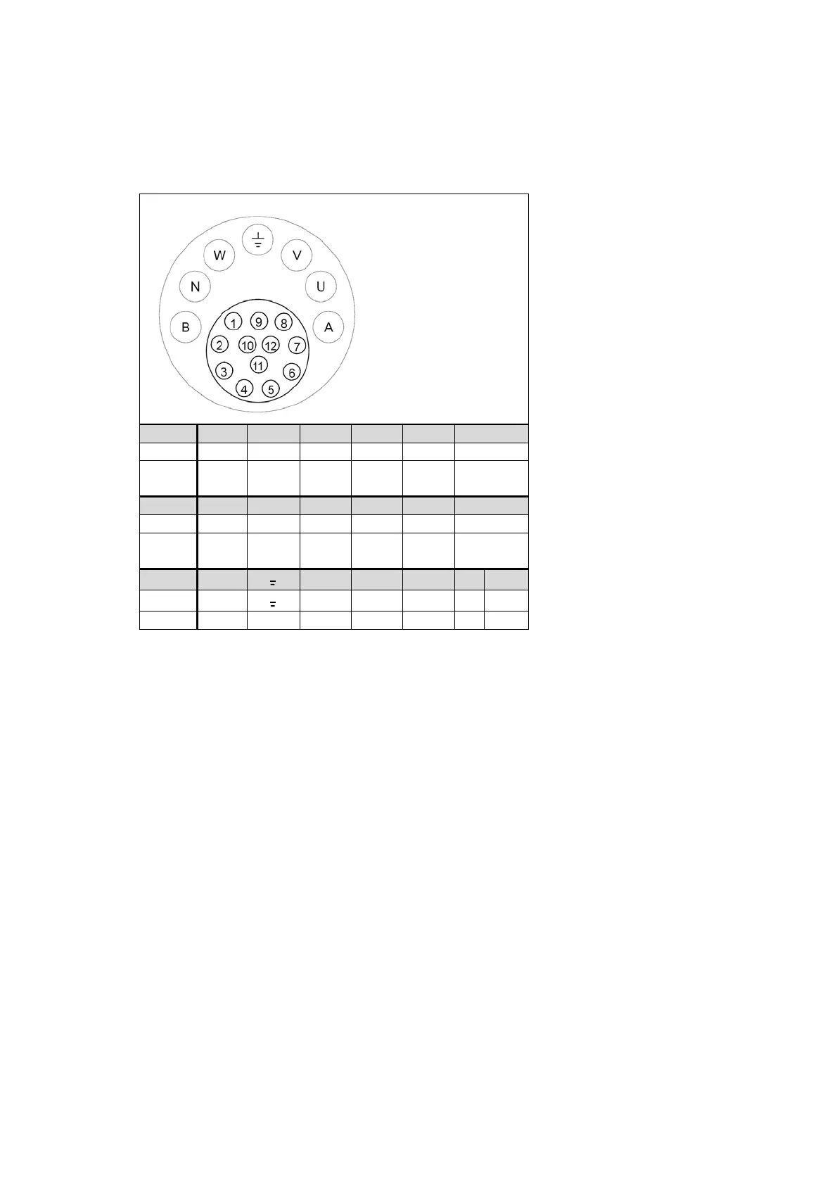
Figure 5: pole assignment of the combination-mounting-box
Outside section: Pin „B to A“ shows the pole assignment for the power terminal and PE-brake.
Inside section: Pin „1 to 12“ shows the pole assignment for resolver and thermal sensor.
Pin 1 2 3 4 5 6
Signal Sin 1 Sin 2 / / / shield
Colour
LTN
yellow blue
Pin 7 8 9 10 11 12
Signal Ref 1 K+ K- Ref 1 Cos 1 Cos 2
Colour
LTN
black /
white
yellow black
red /
white
red black
Pin B
┴
U V W N A
Signal Br. -
┴
U V W Br. +
Colour black red
Contact side
mounting box