Assembly and Installation
Operation Manual Safety I/O Terminals SI4000 / SO4000
Document no.: 5.08009.05
37
of 82
6
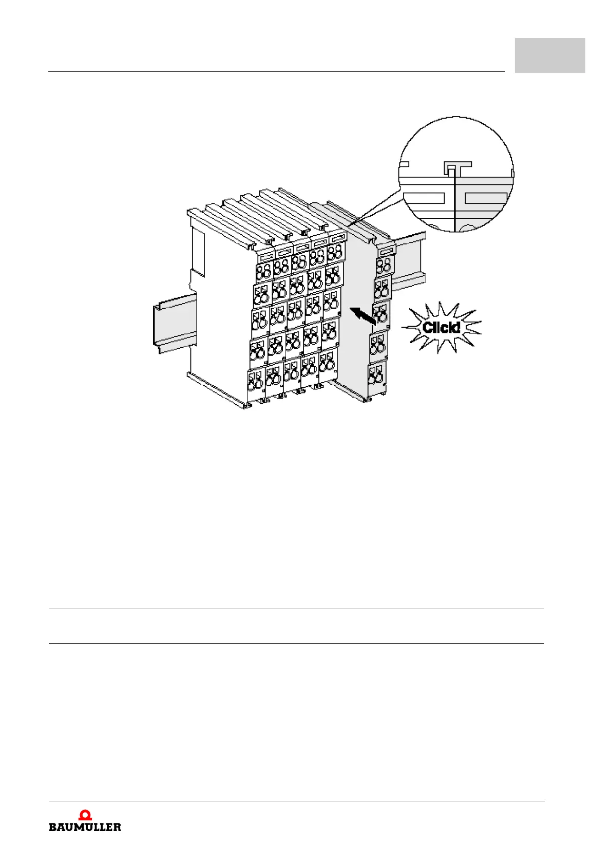
Figure 5: Assembly of the terminals
1 First attach the Fieldbus Coupler to the mounting rail.
2 Th
e Bus Terminals are now attached on the right-hand side of the Fieldbus Coupler.
Join the components with slot and key and push the terminals against the mounting
rail, until the lock clicks onto the mounting rail.
If the Terminals are clipped onto the mounting rail first and then pushed together with-
out slot and key, the c
onnection will not be operational! When correctly assembled, no
significant gap should be visible between the housings.
During the installation of the Bus Terminals, the lo
cking mechanism of the terminals must
not come into conflict with the fixing bolts of the mounting rail.
6.4 Electrical installation
6.4.1 Connections within a bus terminal block
The electric connections between the Bus Coupler and the Bus Terminals are automati-
cally realised by joining the components:
m The six spring contacts of the I/O-Bus deal with the transfer of the data and the supply
of th
e Bus Terminal electronics.