Fig. 35
Control Box
9.7 Making The Electrical Connections
The boiler must be connected to the mains fused 3A 230V
50H
Z supply & control system using cable of 3 core 0.75mm
3183Y multi strand flexible type (see IMPORTANT note
opposite).
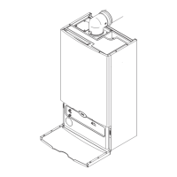
1. Undo the securing screws and lift the case front panel off.
2. Disengage the securing tab and hinge the control box
(Fig. 34) downwards. Undo the terminal block cover securing
screw and remove the cover.
3. Slacken the gland nut in the left of the boiler lower panel
and pass the mains cable through it. Remove the grommet
adjacent to the gland nut, pierce the diaphragm and insert the
cable from the external control system.
4. Leave sufficient slack in the cables to allow the Control Box
to be hinged fully open. Tighten the gland nut and refit the
grommet.
5. Connect the Earth, Permanent Live and Neutral wires to
the terminal strip.
Note: Both the Permanent Live and Neutral connections
are fused.
6. Refer to the instructions supplied with the external
control(s).
IMPORTANT: Any thermostat MUST be suitable for 230V
switching.
7. Remove the link between terminals 1 & 2. The 230V supply
at terminal 2 must be connected to the thermostat. The
switched output from the thermostat must be connected to
terminal 1. (Figs. 35 & 36). If the room thermostat being used
incorporates an anticipator it MUST be wired as shown in Figs.
35 & 36.
Note: When only Low Voltage controls are being used
(connected to Terminal M2) it is still necessary to remove
the link wire !
8. Replace the terminal block cover.
9. See Section 18.0 for details of fitting the manufacturer
supplied Optional Outdoor Sensor and Wired/Wireless
Sensors.
IMPORTANT: Any proprietary OpenTherm control
MUST allow individual adjustment of CH & DHW
temperature.
9.8 Preliminary Electrical Checks
1. Prior to commissioning the boiler preliminary electrical
system checks should be carried out.
2. These should be performed using a suitable meter, and
include checks for Earth Continuity, Resistance to Earth, Short
Circuit and Polarity.
Note: The 230V switched signal for external controls (Frost Stat - Room Stat - Timer)
must always be taken from terminal 2 at the boiler. Live, Neutral and Earth to power
these controls must be taken from the Fused Spur.
IMPORTANT
• Any wiring to the boiler, from either the mains or an external control, MUST be
cable of the following specification:-
0.75mm 3183Y multi strand flexible cable conforming to BS 50525-2-11.
• Cable of the above specification is sufficiently flexible to withstand normal regular
opening and closing of the facia/control box as expected during routine servicing
and other maintenance work.
• Use ONLY cable glands supplied with the boiler, or provided as spares by the
manufacturer.
• Under no circumstances must solid core cable be used as it is not intended for
applications where movement may occur. The use of solid core cable could result
in situations potentially hazardous to health.
• These points must be considered when initially wiring the boiler to the
installation, and if replacing any wiring during the service life of the boiler.