42
13.0 Changing Components
© Baxi Heating UK Ltd 2017
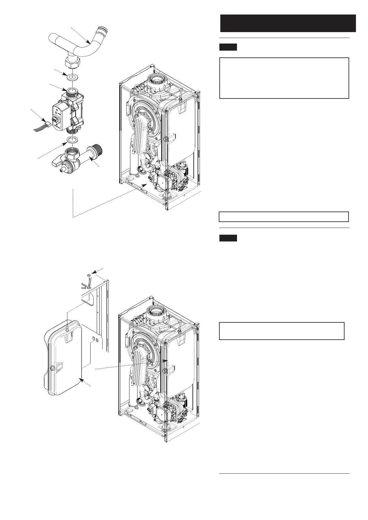
13.20 Gas Valve (Fig. 68)
IMPORTANT: After replacing the valve the CO
2
must be
calibrated as detailed in Section 14.0 Combustion &
Calibration. Only change the valve if a suitable calibrated
combustion analyser is available, operated by a
competent person - see section 12.1.
1. Turn the gas cock off and undo the nut under the boiler.
Retain the washer.
2. Remove the electrical plug from the valve.
3. Undo the nut on the gas feed pipe and ease the pipe aside.
It is recommended that the injector washer is changed as well.
4. Remove the screws securing the gas valve to the boiler
bottom panel.
5. Reassemble in reverse order, ensuring the injector washer is
in place, and perform the Calibration Function & Combustion
Check - see Sections 14.1 & 14.2.
NOTE: Check for gas tightness after replacing gas valve.
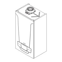
13.21 Expansion Vessel (Fig. 69)
1. Before replacing the vessel it is recommended that the
pressure is checked if there are no apparent leaks or defects.
Expansion Vessel Charge - 1.0 bar
2. To check the charge accurately ensure the system is cold. It
is also necessary to relieve the pressure by draining the boiler.
Using a suitable gauge check the pressure at the valve on the
underside of the vessel. Adjust the pressure as required and
repressurise the system.
Note: A right angled valve extension will aid checking
and repressurising.
3. If the above procedure is unsuccessful replace the vessel as
described below.
4. Close the flow and return isolation taps and drain the
primary circuit.
5. Prise off the securing clip and disconnect the braided hose
from the vessel, taking care as water may still be in the vessel.
6. Ensure that the hose is free of restriction as a boiler with a
blocked hose will exhibit symptoms similar to one with a failed
vessel.
7 . Whilst supporting the vessel undo the locknut and
manoeuvre the vessel out of the boiler.
8. Reassemble in reverse order.
Gas Valve
Gas Cock
Fig. 68
Electrical Plug
Expansion
Vessel
Lock Nut
Fig. 69
Washer
Injector
Washer
Gas Feed
Pipe
NOTE: The Injector Washer MUST
be fitted as shown between the
Valve & Pipe. DO NOT fit the
Injector Washer between the Gas
Cock & Valve