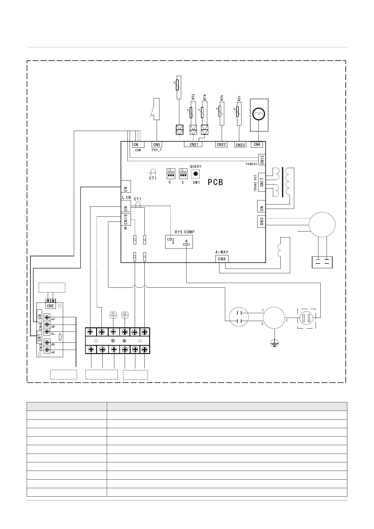
3.4 Electrical diagram of the outdoor unit
Fig.5
MW-4000107-3
Power supply
FA N
White
HIGH SPEED
LOW SPEED
TR
4-WAY VALVE
Ye
llow/Green
HL
HN
N
L
EEV
1
Black
White
B
Red
Red
Y
e
l
l
ow
B
rown
Blue
Blue
Blue
CAP1
Re
d
Blac
k
W
hi
te
Blue
Black
White
Blue
Compressor
capacitor
COMP
Red
Yellow/Green
Compressor outside
overload protection
Red
White
Red
Brown
Black
Yellow
White
Y
e
llow
/Gre
en
LCD
R
T5
L
E-heater
Black
2
3
1
2
3
1
2
20
14
14
Yellow
Red
01
2
Off Peak
-
CN11
CN15
CN10
CN16
HN-in
HL-in
HNHL
Off Peak
2
Red
Tab.15 Key
Connector Description
PCB Control system PCB
LCD Control panel
Power 1 Control panel power supply
TR Transformer
TRANS OUT Transformer outlet
TRANS IN Transformer inlet
EEV Electronic expansion valve
FAN Fan
CAP1 Fan capacitor
Compressor Compressor
3 Technical specifications
16 7740327 - v03 - 03122019