6 Connecting diagrams
6.1 Connecting diagrams with external unit
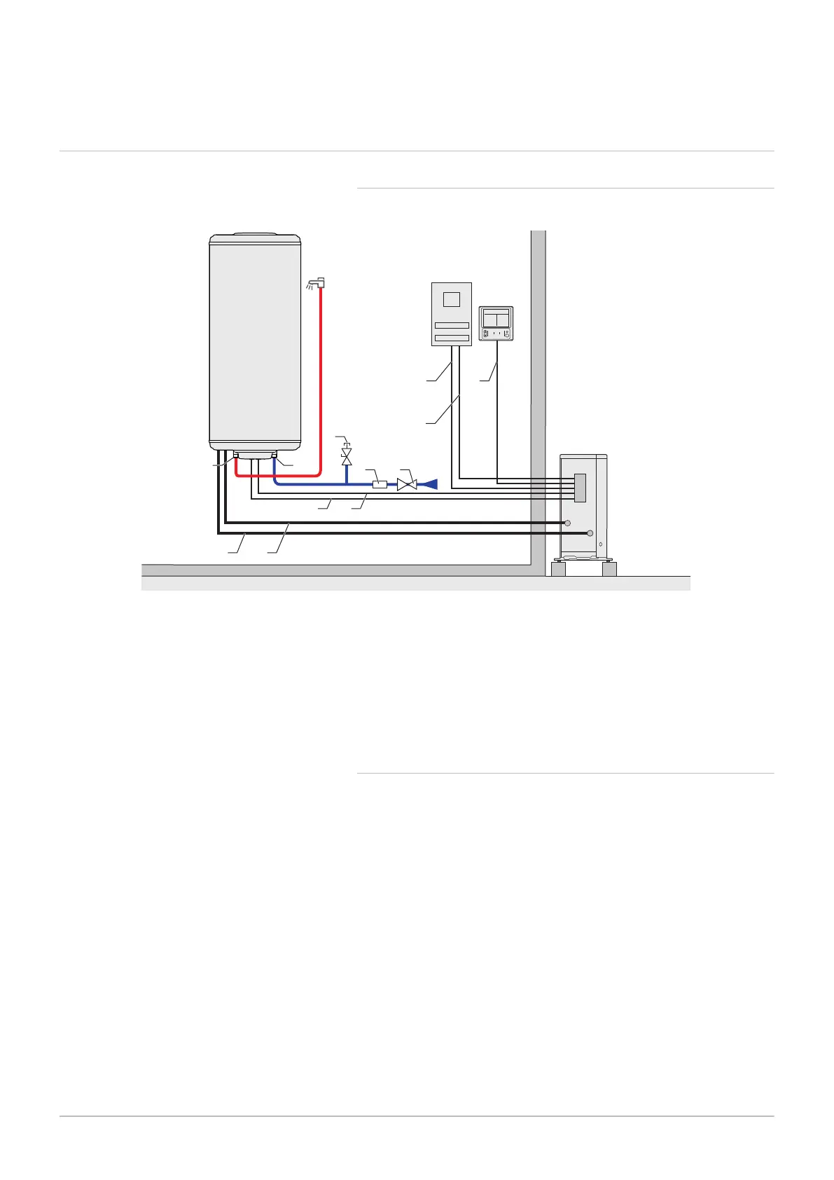
6.1.1 Connection diagram
Fig.18
MW-2000388-2
1 2
3
5 6
8 9
11
B
D
C
A
10 12
4
7
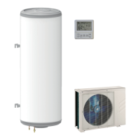
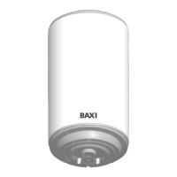
A Domestic hot water tank
B Outdoor unit
C Electrical box
D Control panel
1 Domestic hot water outlet
2 Domestic cold water inlet
3 Power supply cable for the immersion heater
4 Domestic hot water sensor
5 Refrigeration connection out
6 Refrigeration connection in
7 Valve with plug
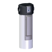
8 Safety unit
9 Pressure reducer
10 General power supply cable
11 Off-peak/peak rate signal cable
12 Control panel communication cable
6.1.2 Connecting diagram with boiler back-up (Hybrid mode)
The Hybrid mode requires a water connection between the domestic hot
water tank and an instant boiler.
6 Connecting diagrams
7740327 - v03 - 03122019 25