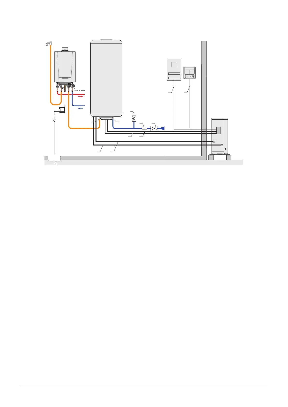
Fig.19
2 30 V
5 0H z
50
100
bar
4
3
2
1
0
°C
120
20
1
204
ON OFF
A
U
T
0
MW-2000616-1
1 2
3
5 6
8 9
B
D
C
10 11
4
A
7
E
A Domestic hot water tank
B Outdoor unit
C Electrical box
D Control panel
E Instant boiler
1 Domestic hot water outlet
2 Domestic cold water inlet
3 Power supply cable for the immersion heater
4 Domestic hot water sensor
5 Refrigeration connection out
6 Refrigeration connection in
7 Valve with plug
8 Safety unit
9 Pressure reducer
10 General power supply cable
11 Control panel communication cable
6 Connecting diagrams
26 7740327 - v03 - 03122019