29
ENENUSER’S MANUAL BR80-BR90
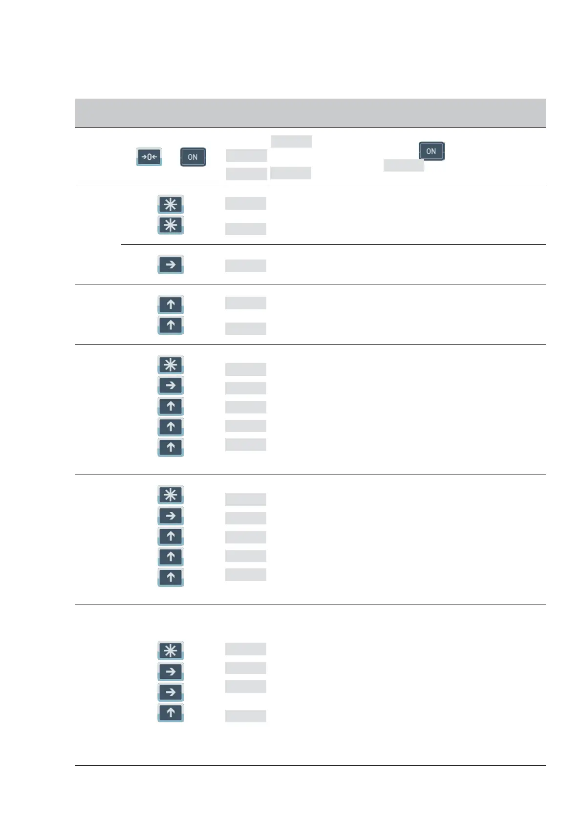
6. CONFIGURATION
Connect load cells to the indicator and set following configuration parameters.
STEP OPERATION DISPLAYING CONTENIDOS
1
Press
and
at same time.
Selftest from
UEr 1.6
0
,to
9
0
Inpoweroffstates,press
ptoturnon,segmentcheck
and displaying
UEr 1.6
edition No 1.5 second.
2
Press
Press
CAL SP
-SET-
Enter of the scale.
Enter the configuration setting modal.
Press
d 1
The number of scale divisions selected.
3
Press
Press
d 2
d 0.1
1 / 2 / 5 / 0.1 / 0.2 / 0.5 / 0.01 / 0.02 / 0.05 / 0.001 / 0.002
/ 0.005 / ...
For example: d=0.1
4
Press
Press
Press
Press
Press
6000
000000
001000
002000
003000
Sets scale F·S
Moves the digit at right.
For example: F·S=3000
5
Press
Press
Press
Press
Press
FLt 10
FLt 00
FLt 10
FLt 20
FLt 30
Sets display Filter parameters: 00-99
The display will updata faster and filter faster as the filter pa-
rameter is changed from 99-00.
For example: FLt=30
6
Press
Press
Press
Press
AUtP00
AUtP00
AUtP00
AUtP10
Sets automatic power off function.
AUtP=00 Not automatic power off.
AUtP=01 Automatic power off.
Digit express the choice of zero trace range (0-9): 1:0.4d 2:0.8d
3:1.2d 4:1.6d 5:2d 6:2.4d
7:2.8d 8:3.2d 9:3.6d.
Decimal digit express the choice of zero set 0.
Decimal digit=0 no zero set at start operation.
Decimaldigit>1zerosetatstartoperation20%F·S.
For example: AUtP=10
(AUtP=10 when leaving the factory)