35
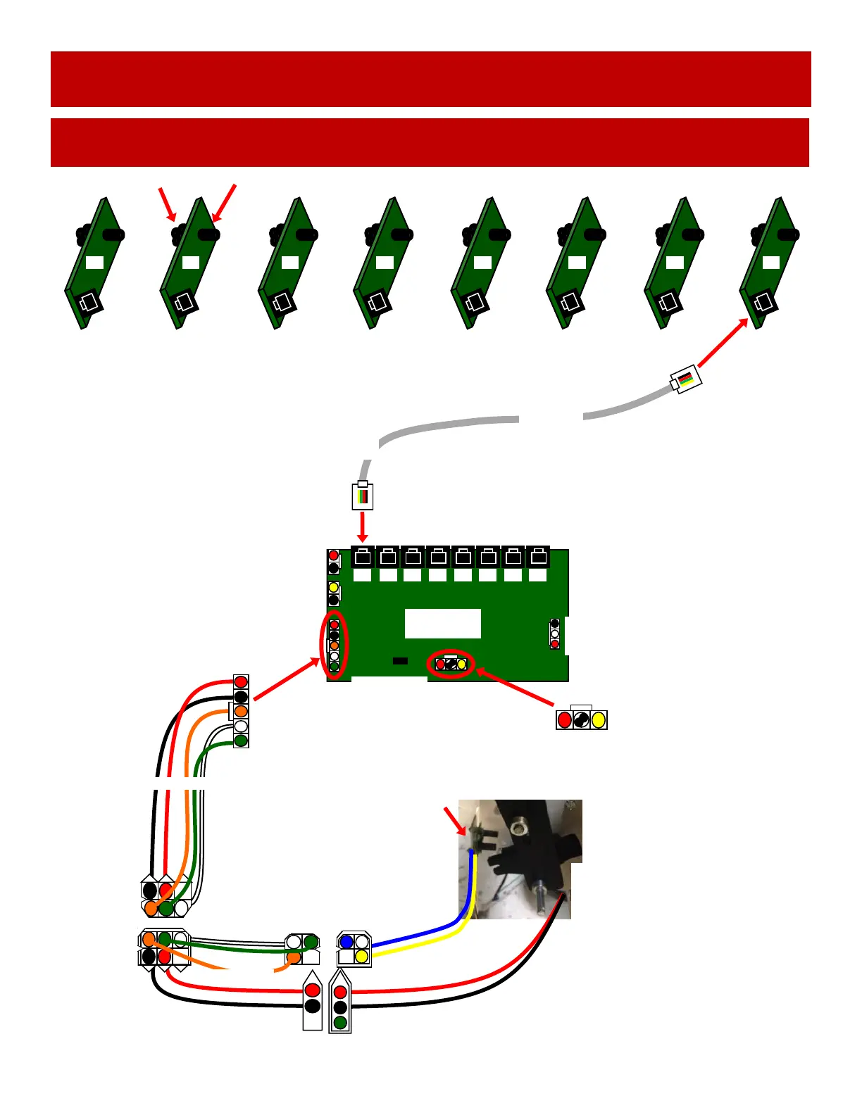
BALL GATE MOTOR, SENSOR AND HOOP SENSORS
WIRING DIAGRAM
AACE15036
AACB10000
Control Board
# 8 # 7 # 6 # 5 # 4 # 3 # 2 # 1
# 8 # 7 # 6 # 5 # 4 # 3 # 2 # 1
A5CB10001
All ball sensor boards have 4 emitters and 1 detector
on opposite sides of the board.
The far left (#1) board can be swapped into a location
with a faulty emitter.
The far right (#8) board can be swapped into a location
with a faulty detector.
Emitters
Detector
Sensor Boards are plugged into the Aux Board
#1 to #1
#2 to #2
Etc..
Similar cable goes to every sensor.
8 cables per game.
A5MO5154
Motor
10 RPM
45-50 Ohms
Pink
Connect-
AACE15015
5 & 12 Volt DC Power in
from Distribution Board
AACE15011
AACE15012
A5CB10001
A5CCORD40
USB Cable
AACE15000
To LED’s under
Baskets
A5CB5190A Sensor
Always 12 Volts DC between the
yellow and blue wires
When sensor is blocked, 5 VDC
between the white and blue wires.
When sensor is not blocked, 0 VDC
between white and blue wires
 Loading...