EasyManua.ls Logo

Bay-Tek Pop the Lock - User Manual

Bay-Tek Pop the Lock
40 pages
Print Icon
To Next Page IconTo Next Page
Loading...
1
Licensed By:
Simple Machine and its logo and Pop The Lock are
trademarks of Simple Machine and are
used with permission.
© Simple Machine. All Rights Reserved.

Questions and Answers

  • L
    Larry HoganAug 16, 2025
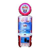
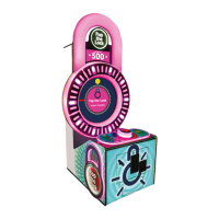
    How to troubleshoot no power on Bay-Tek Pop the Lock?
    • L
      Leslie AndersonAug 16, 2025
      If your Bay-Tek Arcade Game Machine has no power and no lights are on, check the following: Ensure the game is plugged into a working wall outlet. Check and reset the power strip breaker switch or the building circuit breaker. A faulty line filter could also be the issue; consider replacing it (Part # A5FI9010). Also, try changing the plug position or replacing the plug if necessary. For more in-depth diagnostics, refer to the Power Supply diagnostic information.
  • J
    James MccoyAug 18, 2025
    What to do if the dollar bill acceptor is not working on Bay-Tek Pop the Lock Arcade Game Machines?
    • M
      Mark BrownAug 19, 2025
      If the dollar bill acceptor on your Bay-Tek Arcade Game Machine is not functioning, and you see a “Check Newgen Comm” error on the screen, refer to the “Check Newgen Comm” error diagnostic section. Ensure the acceptor cycles the stacker when the game powers up; if not, check the cable connections. Inspect the acceptor slot for dirt or debris and clean it using a bill reader cleaning card (A5CC9000) or by following the “How to Clean Bill Acceptor” instructions. Also, check the wiring from the bill acceptor to the Mini Gen Board (AACE5921), repairing or replacing the wiring harness if needed. Verify that the wires are secure in the J8 connector on the Main Board.
  • M
    mallory59Aug 22, 2025
    Why is my Bay-Tek Arcade Game Machine's bill acceptor and monitor on, but everything else is off?
    • J
      John EsparzaAug 22, 2025
      If the bill acceptor and monitor are on but everything else is off on your Bay-Tek Arcade Game Machine, it could be due to several reasons related to the power supply. First, ensure the unit is properly plugged into the power strip and that the rocker switch is set to the ON position. The power supply might be shutting down due to a 12V overload, potentially caused by a bad motor or a 12-volt short. Refer to the power supply diagnostics to isolate the faulty component. Also, a faulty Power Distribution Board could be the cause; consider replacing it with part number AACB5156.
  • B
    Brandi LawsonAug 25, 2025
    How to fix Bay-Tek Arcade Game Machines that are not coining up?
    • T
      tsmithAug 25, 2025
      Refer to “Check Newgen Comm” error diagnostic section. Check coin switches—both should be wired normally open. If one switch is “closed” the other will not work either. Check wiring to Mini Gen Board. (AACBL4A-DOOR, AACE5920) Check Game Setup Menu. Ensure Coins/Credits per Game is set. Default = 4. Replace faulty Newgen Board. AANEWGEN1-PJ/RBN.
  • E
    Eddie RobbinsAug 27, 2025
    Why is there no sound on my Bay-Tek Pop the Lock Arcade Game Machines?
    • J
      Jim HardingAug 27, 2025
      If there is no sound on your Bay-Tek Arcade Game Machine, first check the Volume & Attract Settings Menu to ensure that the Game Volume & Attract Volume are not set to zero. Next, inspect the audio cable connections from the motherboard to the Newgen board, ensuring they are secure; reseat them if necessary. The relevant cable part numbers are AACE8811, AACE5908, and A5CEAU010. To diagnose whether the motherboard or Newgen board is faulty, unplug the audio jack cable (A5CEAU010) from the motherboard and plug it into an MP3 player to see if the sound is amplified through the speaker. If sound is amplified, the motherboard may be faulty. If there is still no sound, the Newgen board might be the issue. Lastly, check the speaker and replace it if necessary (AACE8811).
  • R
    Robin CamposAug 30, 2025
    What to do if the meters are not working on Bay-Tek Arcade Game Machines?
    • C
      casewilliamAug 30, 2025
      If the meters are not working on your Bay-Tek Arcade Game Machine, first, ensure the correct number of tickets are being dispensed by checking the ticket values in the menu. You can also test the ticket dispense function in the Diagnostic menu. For further assistance, refer to the Tickets not dispensing troubleshooting section. Check the connections and reseat J25 on the Newgen board, using cables # AACE5910 and AACO1000. If the issue persists, consider replacing the counter with part number AACO1000.
  • P
    parkerandresSep 3, 2025
    Why is the colored cabinet lighting not working on my Bay-Tek Pop the Lock?
    • J
      Joseph WheelerSep 3, 2025
      If the colored cabinet lights are not functioning on your Bay-Tek Arcade Game Machine, start by checking the Light Board (AACB5900). Ensure that power is reaching the Light Board from the Power Distribution Board, using cable # AACE5915. Also, verify the connection of the ribbon cable to the Light Board from the Newgen Board, using cable # AACE5933. If an individual LED strip is out, inspect its cable and refer to the “Light Board Wiring Diagram.” To test the LED, swap its connector from one socket to another. If necessary, replace the faulty LED (AACE8622). If problems persist, consider replacing the Minigen board (AANEWGEN1-PJ/RBN).
  • M
    Melissa WhiteSep 5, 2025
    How to fix marquee lights that are not on in Bay-Tek Pop the Lock?
    • S
      Susan MurilloSep 6, 2025
      If the marquee lights on your Bay-Tek Arcade Game Machine are not working, check the connection from the Power Distribution board to the LED strips, ensuring it is properly connected and has continuity. The relevant cable part numbers are AACE5931 and AACE5932. If the connection is good, the LED itself may be faulty and need replacement (AACE5931).
  • J
    James MartinezSep 8, 2025
    What causes the LED white lower cabinet lighting to fail on Bay-Tek Pop the Lock?
    • J
      Jon HallSep 8, 2025
      The LED lights that illuminate the playfield in your Bay-Tek Arcade Game Machine receive 12 Volts DC from the power supply through the Power Distribution Board. Ensure there is a proper connection from the power supply to the Power Distribution Board and then to the LED strips. Check the continuity of the connections using parts AACE5936, AACE5936, AACE5934, and AAPS1013-PTL. Refer to the “AC In, Power Supply Wiring Diagram section” for additional guidance.
  • G
    Garrett CannonSep 12, 2025
    Why are the menu buttons not working on my Bay-Tek Arcade Game Machines?
    • J
      Jesus YoungSep 12, 2025
      If the menu buttons on your Bay-Tek Arcade Game Machine are not working, try swapping the connectors at the two buttons. If the problem remains with the same button, replace the button itself (AAPB2700). Inspect the crimp connections to ensure they are secure. Check the connections from the menu buttons to the main board and verify the continuity of the wires using parts AAPB2700 and AACE5910. If these steps do not resolve the issue, the Newgen Board may be faulty and require replacement (AANEWGEN1-PJ/RBN).

Summary

FACTORY CONTACT INFORMATION

Bay Tek Games Inc. Headquarters

Company address and contact details for Bay Tek Games Inc.

Join the Service First Network

Information on subscribing to the service network for updates and bulletins.

Departmental Contact Numbers

Sales, Parts, and Service department phone and email contacts.

WELCOME TO: Pop The Lock

Game Purchase Congratulations

A welcoming message to the new game owner.

Initial Game Inspection

Procedure for inspecting the game for damage upon arrival.

HOW TO PLAY Pop The Lock

Core Gameplay Mechanics

Instructions on how to play the game by stopping the red bar.

Ticket Earning and Payout

Explanation of how players win tickets for successful hits.

Jackpot Win Conditions

Details on achieving 50 in a row to win the jackpot.

GAME SPECIFICATIONS

Physical Specifications: Weight & Dimensions

Details on the game's net weight, ship weight, width, depth, and height.

Electrical Power Requirements

Information on input voltage range, frequency, and operating current.

Operating Temperature Range

Specified temperature ranges in Fahrenheit and Celsius.

IMPORTANT SAFETY PRECAUTIONS

General Safety Notices and Warnings

Guidelines on modifications, location suitability, and cleaning solvents.

Emergency Response Procedures

Actions to take in case of an emergency, focusing on power disconnection.

SETUP GUIDE WITH HASP

Monitor Face Removal Steps

Instructions for releasing latches and carefully lowering the monitor face.

Chain and S-Hook Disconnection

Procedure for unhooking the S hook and chain from the cabinet.

HASP INSTALLATION SETUP CONTINUED

Marquee Piece Attachment

Steps for carefully lifting and placing the marquee piece.

Marquee Hardware Securing

Using screws and bolts to secure the marquee piece in place.

HASP SETUP: CABLE ROUTING AND CONNECTIONS

Monitor Cable Routing

Routing the cable from the marquee piece through the monitor face channel.

Marquee Cable Connections

Connecting specific cables for the marquee piece (CE5931 to CE5932).

Hasp Piece Placement and Wiring

Positioning the hasp piece and routing its cable through the monitor face.

HASP SETUP: SECURING AND FINAL CONNECTIONS

Hasp Piece Securing Procedure

Using bolts and washers to secure the hasp piece.

Monitor Face Lifting and Wire Routing

Lifting the monitor face and routing all wires before securing.

Top Marquee Light Cable Connection

Connecting the top marquee light cable (CE5931) to CE5932.

HASP SETUP: CIRCUIT BOARD CONNECTIONS AND POWER-ON

Circuit Board Cable Connections

Connecting various cables to the circuit boards and small components.

Final Game Setup and Power On

Replacing the back door, positioning the game, and turning on the power.

GAME HEIGHT ADJUSTMENT OPTIONS

Height Configuration Diagrams

Diagrams illustrating different game height options.

ACCESSING THE MONITOR

Back Door and Cable Removal

Steps to remove the back door and unplug monitor cables.

Monitor Latches Release Procedure

Releasing the four latches to detach the monitor face.

Vacuum Form Lowering for Monitor Access

Carefully lowering the vacuum form to expose the monitor face.

MAINBOARD DIP SWITCH SETTINGS

Dip Switch Bank Location

Identifying the location of the dip switch bank on the mainboard.

Default Dip Switch Configuration

Table showing factory default settings for dip switches.

GAME MAIN MENU NAVIGATION

Accessing and Navigating Main Menu

How to access and use the main menu with the buttons.

Main Menu Functions Overview

Listing of the primary functions available in the main menu.

Description of Main Menu Options

Explanations for clearing credits, resetting defaults, and muting.

VOLUME AND ATTRACT SETTINGS

Adjusting Game and Attract Volumes

Settings for attract volume, game volume, and jackpot volume.

Attract Timing and Music Configuration

Settings for attract timing and background music volume.

GAME SETTINGS CONFIGURATION

Overview of Game Settings

Explanation of training attempts, continue time, and game mode.

Detailed Game Settings Options

Table detailing options for training attempts, continue time, and game mode.

ADVANCED GAME SETTINGS CONFIGURATION

Advanced Game Play Settings

Configuration of continues allowed, dial speed, and acceleration.

Detailed Advanced Game Settings

Table detailing options for continues, dial speed, and acceleration.

PAYOUT SETTINGS CONFIGURATION

Overview of Payout Settings

Explanation of credits per play, ticket values, and jackpot settings.

Detailed Payout Menu Options

Table detailing options for credits, tickets, and accumulation.

TICKET PATTERN CONFIGURATIONS

Ticket Tix;Hit and Bonus Amounts

Table showing average tickets per game, TIX/HIT, and bonus amounts.

GAME STATISTICS TRACKING

Current Game Statistics Display

Display of total games played, tickets, continues, and wins.

Definitions of Game Statistics

Explanations for each metric shown in the statistics menu.

CIRCUIT BOARD LAYOUT

AAMB9 A-SHD Motherboard Layout

Identification and layout of the main motherboard.

Circuit Board Component Connections

Diagram showing connections for LEDs, buttons, and other components.

Power and Interface Board Identification

Identification of power distribution and interface circuit boards.

MAINBOARD CONNECTOR PINOUT

Mainboard Pinout Diagram

Visual representation of the mainboard's connector pin assignments.

Specific Connector Pin Assignments

Details for J10 (SPI Out) and J11-J14 (Chase Lights) pinouts.

MAINBOARD PINOUT GUIDE AND MAPPING

Pin Type to Purpose Mapping Guide

Guide mapping pin types to their functions and connector pins.

Detailed Connector Pin Assignments

Comprehensive pin assignments for various mainboard connectors.

TROUBLESHOOTING GUIDE: POWER AND BILL ACCEPTOR

Troubleshooting No Power or Lights

Steps to diagnose and fix issues with game power and lighting.

Troubleshooting Bill Acceptor Functionality

Steps to resolve problems with the Dollar Bill Acceptor.

Troubleshooting Meter Issues

Steps for resolving issues with ticket and game meters.

TROUBLESHOOTING GUIDE: COIN UP AND SOUND

Troubleshooting Game Coin-Up Failures

Steps to diagnose why the game is not accepting coins.

Troubleshooting No Sound Issues

Steps to resolve problems related to the game's audio output.

Resolving Newgen Comm Errors

Steps to fix "Newgen Comm Error" and credit meter malfunctions.

TROUBLESHOOTING GUIDE: LIGHTING AND BUTTONS

Troubleshooting Cabinet Lighting

Steps to fix issues with white and colored cabinet LED lighting.

Troubleshooting Marquee Lights

Steps to diagnose and repair non-functional marquee lights.

Troubleshooting Menu Button Failures

Steps to fix problems with the game's menu buttons.

TROUBLESHOOTING GUIDE: TICKETS AND BUTTONS

Troubleshooting Ticket Dispensing

Steps for resolving issues with ticket dispensing amounts.

Resolving Low Tickets Message

Actions to take when the "Low Tickets" message appears.

Troubleshooting Buttons and Lights

Diagnosing faulty buttons and non-blinking button lights.

TROUBLESHOOTING GUIDE: MONITOR ISSUES

Troubleshooting Monitor No Signal

Steps for when the monitor displays "No Signal Detected".

Troubleshooting Monitor No Power

Steps to resolve issues where the monitor has no power.

Troubleshooting Monitor Error Screens

Steps for diagnosing common monitor error messages.

WIRING DIAGRAMS: AC POWER AND SUPPLY

AC Power Input and Distribution Wiring

Diagram showing AC power entry, line filter, and distribution connections.

Power Supply to Component Wiring

Wiring connections from the power supply to the motherboard and TV.

WIRING DIAGRAMS: LIGHT BOARD

Light Board LED Connections

Diagram illustrating connections to the light board for various LEDs.

WIRING DIAGRAMS: COIN MECH AND CONTROLS

Coin Mech, Counter, and Dispenser Wiring

Wiring for coin mechanism, ticket counter, and dispenser.

Menu Buttons and Speaker Wiring

Wiring diagram for menu buttons, game stop light, and speaker.

WIRING DIAGRAMS: CHASE BOARD AND BILL ACCEPTOR

Chase Board, Coin Switch Wiring

Wiring for the chase board, coin switches, and marquee LEDs.

Bill Acceptor and Ground Wiring

Wiring for the bill acceptor, game ground, and power strip.

WIRING DIAGRAMS: MOTHERBOARD COMMUNICATIONS

Motherboard Communication Wiring

Diagram showing communication links between the motherboard and other boards.

Monitor and Audio Connections Wiring

Wiring for monitor HDMI and audio jack connections to the motherboard.

POWER SUPPLY DIAGNOSTIC PROCEDURES

Verifying AC Power and Connections

Steps to check AC power, rocker switch, and fan operation.

Verifying Power to Motherboard

Checking if the motherboard is receiving 12 volts from the power supply.

Minimizing Load and Isolating Shorts

Procedure to isolate short circuits by removing load from the power supply.

BILL ACCEPTOR (DBA) DIAGNOSTICS

Checking Bill Acceptor Power

How to verify if the bill acceptor is receiving power.

Bill Acceptor Dip Switch Settings

Configuring dip switches on the bill acceptor for proper function.

Interpreting Bill Acceptor Error Codes

Guide to understanding and resolving bill acceptor error codes.

COMPREHENSIVE PARTS LIST

Parts List: Part Numbers and Descriptions

A detailed listing of all game components with their part numbers.

VISUAL PARTS IDENTIFICATION GUIDE

Identifying Parts via Images

Pictures of various game parts for visual identification.

GAME DECALS PLACEMENT DIAGRAM

Diagram of Decal Locations and IDs

Visual guide showing placement and part numbers for all game decals.

TECHNICAL SUPPORT AND SERVICE POLICIES

Circuit Board Repair and Replacement Options

Options for repairing or advancing replacement of circuit boards.

Guidelines for Purchasing Spare Parts

Information on buying spare circuit boards to maintain games.

Policies on Returns, Credits, and Fees

Procedures and fees related to item returns and credits.

Bay-Tek Pop the Lock Specifications

General IconGeneral
Game TypeRedemption
CategoryArcade Game Machines
Skill RedemptionYes
ManufacturerBay-Tek
Players1
Ticket DispenserYes
SoundStereo

Related product manuals