EasyManua.ls Logo

BDE BDE-2007 - User Manual

BDE BDE-2007
28 pages
Print Icon
To Next Page IconTo Next Page
Loading...
1
CHAPTER 1 INTRODUCTION
§ 1-1 Items In Carton
The carton in which the BDE-2007 is delivered contains:
1. Indicator. 2. Accessory pack (In bag). 3. Manual.
CHAPTER 2 INSTALLATION
§ 2-1 Best Conditions For Use
When installing and wire connecting on BDE-2007, please follow the guidelines
below:
Before connecting the Electric Power Supply, please identify the input Electric
voltage type is DC 12V or DC 24V.
The Operation Temperature shall range within 0 ~ 45 , please DO not install in
any place of direct sun-light. Due to the minute output signal from Load Cell,
please use isolated cables. Also, separate the Load Cell cable from the power
supply cable and control I/O cables.
The input power shall be DC 12V or DC 24V±10%, if the Electric Power Supply is not stable or the
interference signal exists, that may cause uncertain actuation or reaction, even damage.
Therefore, please utilize Electric Power Supply Stabilizer of adequate capacity.
§ 2-2 Connecting the Load Cell
Do not turn on your power until you have completely connected the load cell.
To connect your load cell to the weighing
Indicator use a six-wire cable with shield - connect the wires as indicated above. If
the BDE-2007 / BDE-2007 is located near the Load Cells (Within five meters or a
few yards) you may use a 4-wire cable with shield, but first connect screws 1&2 and
3&4 with independent jumper leads.
The analogue output from the Load Cell and input/output signals are sensitive to
electrical noise. Do not bind these cables together as it could result in cross-talk
interface. Please also keep them away from AC power cables.
Screw Signal
1
Positive Excitation Voltage, (EXC+)
2
Positive Sense Voltage, (SEN+)
3
Negative Sense Voltage, (SEN-)
4
Negative Excitation Voltage, (EXC-)
5
Positive Signal Voltage, (SIG+)
6
Negative Signal Voltage, (SIG-)
7
Shield, (SHD)
Open the case, there is a
j
umpe
r
S1near the
transformer, please insert
a short-circuit pin to the
available side.
Question and Answer IconNeed help?

Do you have a question about the BDE BDE-2007 and is the answer not in the manual?

Summary

Chapter 1: Introduction

1-1 Items In Carton

Lists the items included in the BDE-2007 product carton.

Chapter 2: Installation

2-1 Best Conditions For Use

Guidelines for optimal installation and operating environment.

2-2 Connecting the Load Cell

Procedure for connecting the load cell to the indicator.

2-3 Front and Rear Panel Dimensions

Physical dimensions of the BDE-2007 indicator.

Chapter 3: Specifications

3-1 Analog Input and A;D Conversion

Analog input capabilities and A/D conversion details.

3-2 General

General specifications including power and operating temperature.

3-3 Display and Signs

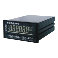
Front panel display elements and status indicators.

3-3-2 Operation Modes

Description of the indicator's different operational modes.

Chapter 4: System Functions

4-1 System Check

Procedure for performing a system check on the indicator.

4-2 Functions

Accessing and changing function settings and parameters.

4-3 Calibration

Step-by-step guide for calibrating the indicator.

Calibration Errors

List of calibration error codes and their solutions.

4-4 System Initialize

Steps for initializing system settings.

4-5 Accumulation

How to display and clear accumulated data.

Chapter 5: Set Points

5-1 Set Points

Changing set point codes and their values.

5-2 Batching Modes

Description of the indicator's various batching modes.

Chapter 6: Options

6-1 I;O Interface

Input/output interface options and pin assignments.

6-2 Serial Interface

RS-232 and RS-485 serial interface specifications and pin assignments.

PC Connection and Data Transfer

PC connectivity, data formats, and command lists for communication.

6-3 Analog Output

Analog output configurations (4-20mA and 0-10V).

6-4 Relay Control Interface OP-08

Relay control interface option OP-08 details.

6-5 Modbus

Modbus communication protocol implementation and data registers.

Overview

The BDE-2007 is a weighing indicator and controller designed for various industrial weighing applications. It comes with the indicator unit, an accessory pack, and a manual.

Function Description

The BDE-2007 primarily functions as a weighing indicator, displaying weight measurements, and as a controller for batching operations. It supports both normal weighing and loss-in-weight batching modes, with options for customer-programmed or built-in automatic programs. The device can be integrated into a system via serial interfaces (RS-232C, RS-485) and offers analog output for control purposes. It also includes features for system checks, calibration, and accumulation of weight data.

Important Technical Specifications

General:

  • Power Requirements: DC 12V or 24V ±10%, 400mA.
  • Net Weight: 0.4 kg.
  • Operation Temperature: -10℃ to 45℃.
  • Maximum Physical Dimensions: 160 (D) x 99 (W) x 49 (H) mm.
  • Humidity: 85% (non-condensing).

Analog Input and A/D Conversion:

  • Input Sensitivity: 0.12 µV/D or above.
  • ZERO Adjustment Range: 0 ~ 20mV.
  • Load Cell Excitation: DC5V ±5%, 120mA, with remote sensing. Can connect up to 8 load cells of 350Ω.
  • Non-Linearity: 0.01% F.S.
  • A/D Conversion Method: ΔΣ.
  • A/D Resolution: 1/1,000,000.
  • A/D Conversion Rate: 120 Times/Sec.
  • Max. Load Cell Input Voltage: 20mV.
  • ZERO Temperature Compensation: ±(0.2 µV + 0.001% of Dead Load)/℃ TYP.
  • SPAN Temperature Compensation: ±0.001% / ℃ TYP.
  • Max. Resolution: 1/30,000.

Display:

  • 6-digit display for positive values.
  • Weight indication in kg, t, or lb.
  • Status indicators for ZERO, M.D. (unstable), NET, TARED.
  • Keypad for MODE, ZERO, TARE, G/N functions.
  • DC Voltage low indicator.

Digital Filter (F003):

  • Offers 7 stages of filtering from "No stage Weak" to "7th stage Strong" to adjust for environment vibration and response speed.

Motion Detection (F005):

  • Settings for stable operation or various sensitivity levels (e.g., 0.5 SEC 1 DIV to 1 SEC 8 DIV).

Automatic ZERO Tracking Compensation (F006):

  • Options from OFF to 2 SEC 4 DIV for automatic zero adjustment.

ZERO & TARE keys Availability (F007):

  • Keys can always work or only when the display is stable.

TARE key Availability (F008):

  • TARE key can always work or not work if GROSS is negative.

Accumulation Availability (F009):

  • Options for OFF, Stable, Manual, or Control Input (Modbus) accumulation.

Batching Modes (F101):

  • Customer Programmed Control Mode: Normal Batching (F101=1) and Loss-in-Weight Batching (F101=2).
  • Built-in Automatic Program Mode: Normal Batching (F101=3) and Loss-in-Weight Batching (F101=4).
  • Multiple-Ingredient Batching (F101=5).

Timer-Comparator Inhibitor (F102):

  • Set between 0.0 to 2.0 Sec (initial 0.0 Sec), applicable to batching modes 3 and 4.

Timer-Finish Signal (F103):

  • Set between 0.0 to 9.9 Sec (initial 0.0 Sec).

Pulse Width of Finish Signal (F104):

  • Set between 0.0 to 2.0 Sec (initial 0.5 Sec). Stable at 0.0 Sec for F101 settings 3 or 4.

Output 8 (F105):

  • Indicates Unstable (0) or Error (1).

Input by (Batch start/stop) (F106):

  • Panel key, BCD Input, or Serial Input/Modbus.

Memory Automatic Free Fall Compensation (F108):

  • Yes or Not Memory.

Serial Interface (OP-02):

  • EIA-RS-232C 12V: Half Duplex, Asynchronous Transmission. Baud Rates: 1200, 2400, 4800, 9600, 19200BPS. Data Bits: 8 or 7. Parity: non-parity, odd/even. Stop Bit: 1. Output Code: ASCII.
  • EIA-RS-485: Half Duplex, Asynchronous Transmission. Baud Rates: 2400BPS, 4800BPS, 9600BPS, 19200BPS, 38400BPS. Data Bits: 8 or 7. Parity: non-parity, odd/even. Stop Bit: 1. Output Code: ASCII.

Analog Output (OP-05):

  • Output Data (F500): 4~20 mA or 0~+10 V.
  • Output Mode (F501): Same as display, GROSS Weight, NET Weight.
  • Loss-in-weight Absolute Value (F502): Not read or BDI-2001B reads Absolute Value.
  • Output current when display ZERO (F503): 0.0 through 99.9 (initial 4.0).
  • Output current at Full Capacity (F504): 0.0 through 9.99 (initial 20.0).
  • Range: 4~20mA (possible: 2~22mA) or 0~+10V (possible: -1.25~11.25V).
  • Resolution: Min. 1/3000.
  • Temperature Coefficient: ±(0.015% / Cof rdg + 0.01mA) / ℃.
  • Max. Resistance Load: 500Ω (for 4-20mA) or 5KΩ (for 0-10V).

Relay Control Interface (OP-08):

  • Power: Standard DC12 from outside.
  • Input (IN): 8 pins, Input Common Pin: COM1.
  • Output (OUT): 8 pins, Type: for RELAY. Max. Load: 250VAC, 30VDC, 3A. Output Common Pin: COM2. RELAY durance: About 100,000 Times. LED light ON when work.
  • SSR Type: Max. Load: 24~280VAC, 3A (Only for AC).

Usage Features

Installation and Wiring:

  • Requires identification of input electric voltage (DC 12V or DC 24V) before connection.
  • Operates within 0℃ ~ 45℃; avoid direct sunlight.
  • Recommends isolated cables for load cell signals and separation from power/control I/O cables to prevent interference.
  • Suggests using an Electric Power Supply Stabilizer for unstable power or interference signals.
  • Load cell connection uses a six-wire cable with shield. For short distances (within 5 meters), a 4-wire cable with shield can be used by jumpering screws 1&2 and 3&4.
  • Analog output and input/output signals are sensitive to electrical noise; avoid binding these cables together or with AC power cables.
  • A jumper (S1) near the transformer needs a short-circuit pin inserted to the available side.

Operation Modes (3-3-2 Operation Modes):

  • Pressing the MODE key for more than 2 seconds cycles through:
    • MODE0 (No light): Normal Weight display mode.
    • MODE1 (Red light): Batch operation mode.
    • MODE2 (Green Light): Set point and Accumulation Mode.
    • MODE3 (Orange light): Not In Use.

System Check (4-1 System Check):

  • A comprehensive check procedure after installation or changes, including:
    • Power OFF, ensure SET switch is OFF.
    • Power ON, press MODE, then ZERO for >2 seconds to display F-CSET→FUNC.
    • Press TARE to show CHECK.
    • Press MODE to check 7 Segment LEDs.
    • Slide Set 1 ON, then press MODE to check MEMORY (EEPROM) for I-0 (system error).
    • Check Input/Output (I-O) by short-circuiting pins on the 25-Pin D output panel.
    • Check keypad (KEY 01~KEY 4).
    • Finish by sliding SET OFF and pressing MODE with ZERO for 1 second to return to normal mode.

Functions (4-2 Functions):

  • Access function settings (F-CSET→FUNC) by pressing MODE with ZERO for >2 seconds.
  • Navigate through F000, F200, F300, F400, F500 using TARE or G/N keys.
  • Enter categories by pressing MODE.
  • Exit function settings by pressing ZERO for >2 seconds.

Calibration (4-3 Calibration):

  • A step-by-step process for setting minimum division, decimal point, maximum capacity, ZERO adjust, and SPAN calibration.
  • Minimum Division: Set using +/- keys (01, 02, 05).
  • Decimal Point: Set using +/- keys (01, 02, 05).
  • Maximum Capacity: Set using < or +/- keys (01, 02, 05).
  • ZERO Adjust: Clear weighing device, press MODE.
  • SPAN Calibration: Place calibration mass, input weight value using < or +/- keys, press MODE.
  • Includes a list of calibration errors (C.Err 1 to C.Err 12) with troubleshooting guidance (e.g., resolution exceeds limit, load cell output too large/small, incorrect mass entry, reversed signal pins).

System Initialize (4-4 System Initialize):

  • Procedure to initialize the system: Power OFF, slide SET 1 ON, screen shows CAL, press TARE until init, press MODE, screen shows NO, press + key to show YES, press MODE to confirm END, slide SET OFF.

Accumulation (4-5 Accumulation):

  • Display Accumulation: In MODE 2, press TARE to show total count, press TARE again for accumulation.
  • Clear Accumulation: Press TARE for >2 seconds to show CLR A.C., press MODE to clear.

Set Points (5-1 SET POINTS):

  • Allows setting of Final, SP1, SP2, FREE, Hi, and Lo values using +/-/< keys and confirming with MODE.

Batching Modes (5-2 BATCHING MODES):

  • Detailed operational sequences for Normal Batching and Loss-in-Weight Batching, covering steps from hopper empty to next batching event, including signal outputs (SP1, SP2, FREE, ZERO Band, Finish) and inputs (TARE, Start, Abort).

Maintenance Features

System Check:

  • The system check procedure (4-1) serves as a diagnostic tool to locate unexplained system errors after installation, moving the device, or connecting/disconnecting attachments.

Calibration Errors:

  • The manual provides a comprehensive list of calibration errors (C.Err 1 to C.Err 12) with specific remedies, such as adjusting resolution, adding resistors, checking load cell connections, and verifying entered values. This aids in diagnosing and correcting calibration issues.

Error Messages (MODBUS):

  • MODBUS communication includes error codes (E01-E05) for command format, data, acceptance, execution, and busy status, facilitating troubleshooting of serial communication.

Power Supply Stabilization:

  • Recommends utilizing an Electric Power Supply Stabilizer if the electric power supply is not stable or if interference signals exist, to prevent uncertain actuation, reaction, or damage.

Cable Management:

  • Emphasizes using isolated cables for load cell signals and separating them from power/control I/O cables to minimize interference and ensure reliable operation. This proactive measure helps in maintaining signal integrity and preventing issues.

BDE BDE-2007 Specifications

General IconGeneral
BrandBDE
ModelBDE-2007
CategoryController
LanguageEnglish