BEA | 3rd-5th Floor Tower B / No.10 Jiu Xian Qiao North Road, Chao yang District, Beijing
| T +86 10 57761616 / F +86 10 62628775
| INFO@BEA.BE |
1
1
1
2
1
2
1
2
1
1
2
1
1
1
2
3
1
2
Angleur, November 2010 Jean-Pierre Valkenberg, Authorized representative
The complete declaration of conformity is available on our website: www.bea.be
LED-SIGNALS
The ORANGE LED
fl ashes 1 x.
The ORANGE LED
fl ashes every second.
The ORANGE LED
is on.
The RED LED fl ashes
quickly after a setup.
The RED LED
lights up
sporadically.
The GREEN LED
lights up
sporadically.
The reaction of
the door does not
correspond to the
LED-signal.
The sensor goes into
security mode.
The sensor signals
an internal fault.
The sensor encounters
a memory problem.
The sensor vibrates.
The sensor sees the door
during the setup.
The sensor sees the door.
The sensor vibrates.
Ghosting
The sensor sees the door
or other moving objects.
Cut and restore power supply.
Cut and restore power supply.
If orange LED lights up again, replace sensor.
Check the angle of the IR-curtains.
Launch a new setup.
Attention: Do not stand in the detection fi eld!
Check wiring.
Check if the sensor is fastened fi rmly.
Check position of prism and cover.
Change radar antenna angle.
Check if the sensor is fastened fi rmly.
Check position of cable and cover.
Change radar antenna.
Change radar fi eld size (sensitivity).
Remove the objects if possible.
Launch a setup and adjust the IR angle.
Cut and restore power supply.
If orange LED fl ashes again, replace sensor.
Only for EC countries: According to the European Guideline 2002/96/EC for Waste Electrical and Electronic Equipment (WEEE)
SAFETY INSTRUCTIONS
The manufacturer of the door system is responsible for carrying out a risk assessment and installing the sensor and the door system
in compliance with applicable national and international regulations and standards on door safety.
Only trained and qualifi ed personnel may install and setup the sensor.
The warranty is void if unauthorized repairs are made or attempted by unauthorized personnel.
Avoid touching any electronic and optical components.
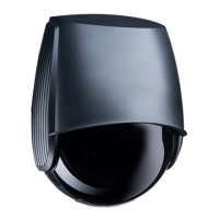
C8
2
1
5
7
8
9
6
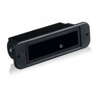
TECHNICAL SPECIFICATIONS
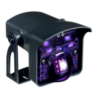
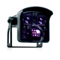
1. Cover
2. Front cover
3. Infrared lens
4. Microwave antenna
5. IR-curtain ajustment screw
DESCRIPTION
Presence
Typical response time: <128 ms (max. 500 ms)
Active infrared with background analysis
Spot diameter: 6 cm (typ)
Number of spots: 24 by curtain
Number of curtains: 1
From -5 ° to +8 ° (adjustable)
Relay (free of potential)
Max. contact voltage: 42 V AC/DC
Max. contact current: 1 A (resistive)
Max. switching power: 30 W (DC)/60 VA (AC)
0.5 s
EN
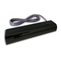
Opening & safety sensor
for automatic sliding doors
12 V - 24 V AC +/-10% ; 12 V - 30 V DC 0%/+10%
< 3 W
1.8 m to 3 m
-25 °C to +55 °C
IP54
Supply voltage:
Power consumption:
Mounting height:
Temperature range:
Degree of protection:
Motion
Min. detection speed: 5 cm/s
Microwave doppler radar
Transmitter frequency: 24.150 GHz
Transmitter radiated power: < 20 dBm EIRP
Transmitter power density: < 5 mW/cm2
From 15 ° to 45 ° vertical (adjustable)
Relay (free of potential)
Max. contact voltage: 42 V AC/DC
Max. contact current: 1 A (resistive)
Max. switching power: 30 W (DC)/60 VA (AC)
0.5 s
Detection mode:
Technology:
Angle:
Output:
Hold time output signal:
GREEN
LED
RED
LED
cations are subject to changes without prior notice
All values measured in optimal conditions.
Other use of the device is outside the permitted purpose and can not be
guaranteed by the manufacturer. The manufacturer cannot be held responsible for
incorrect installations or inappropriate adjustments of the sensor.
6. Dip switch
7. LED
8. Microwave sensitive potentiometer
9. Cable plug
4
3
087