Do you have a question about the BEA BODYGUARD-T and is the answer not in the manual?
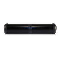
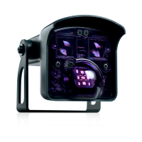
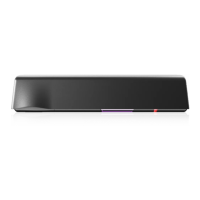
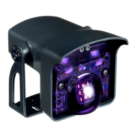
Introduces the Bodyguard-T presence sensor and its monitoring capability.
Specifies the recommended and maximum installation height for the sensor.
Details the available mounting angles for the sensor, including factory default.
Defines the required power supply voltage and tolerance for the sensor.
States the operational frequency range for the sensor.
Lists the maximum voltage, current, and switching power for the sensor's output.
Specifies the adjustable duration the relay will remain active.
Defines the environmental temperature range for sensor operation.
Describes the sensor's resistance to electrical and radio frequency interference.
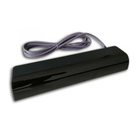
Provides the standard cable length and physical weight of the sensor unit.
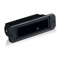
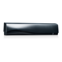
Lists the physical dimensions, materials, and housing color of the sensor.
Provides essential tips for securely mounting the sensor to avoid issues like vibrations.
Details sensor mounting for single, dual-egress, and simultaneous pair door applications.
Outlines safety signal requirements per ANSI 156.10 for door control systems.
Emphasizes correct grounding, qualified personnel, and post-installation testing.
States that the warranty is invalid if unauthorized repairs are made or attempted.
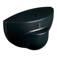
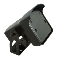
Details when Bodymounts are required for installations and the steps to follow.
Guides through the process of disassembling the sensor for preparation, removing caps and lenses.
Covers mounting the sensor directly to a door frame/header or to a Bodymount.
Provides instructions on how to slide the circuit board back into the sensor extrusion.
Describes how to make angle adjustments for optimal detection patterns at different angles.
Details wiring procedures for both monitored and non-monitored door control systems.
Maps 10-pin connector details and advises on wiring the sensor to specific modules.
Explains the function and default setting of the monitoring DIP switch for system compatibility.
Describes applying power to the sensor and the LED indication during setup.
Offers troubleshooting advice for data problems and sensor recycling when using a lockout module.
Introduces programming functions using the remote control for various sensor parameters.
Lists and briefly explains the available operational modes and infrared frequency settings.
Explains different door control modes and procedures for unlocking, locking, and inquiring about settings.
Provides detailed settings for Sensitivity, Hold Time, Auto-Learn Time, Pattern Width, and Pattern Depth.
Details Immunity settings and available setup options like quick set-up and factory defaults.
Offers steps to minimize interference between sensors in dual-egress setups by adjusting frequency and patterns.
Explains how to program the sensor using its physical push-buttons for key parameters.
Maps Red LED flashes to parameters and their corresponding Green LED status indicators for programming.
Explains pattern chart representation and displays various width patterns with numerical ranges.
Shows different depth patterns, including variations without the first row of detection.
Addresses problems during initial powering and sensor setup, including voltage and detection errors.
Covers issues with door opening after setup, detection, improper wiring, and safety beams.
Troubleshoots sensor reaction to remote, LED indications, DIP switch settings, and monitoring issues.
States BEA's disclaimer and recommends certifications for installers and service technicians.
Outlines installer duties, including risk assessment, safety inspections, and compliance with standards.
| Type | Motion Detector |
|---|---|
| Output | Relay |
| Housing Material | ABS |
| Activation Method | Motion Detection |
| Battery | No |
| Battery Life | Not Applicable |
| Material | ABS |