75.5351.02 EN 20080317 (75.5350) Page 1 of 7
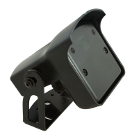
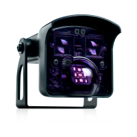
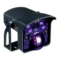
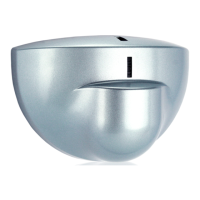
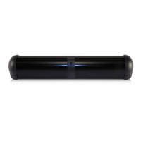
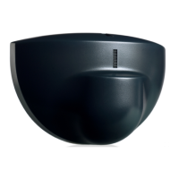
FALCON & FALCON XL
USER'S GUIDE
MOTION SENSORS FOR INDUSTRIAL DOORS
• FALCON: for high mounting • FALCON XL: for low mounting
Technology: Microwave and microprocessor
Transmitter frequency: 24.125 GHz
Transmitter radiated power: <20 dBm EIRP
Transmitter power density: < 5 mW/cm²
Mounting height
FALCON: from 11.5 to 23’
FALCON XL: from 6.5 to 11.5’
Tilt angle: 0° to 180° in elevation
Detection zone (typical)
Wide pattern (FALCON XL): 13’ (W) x 6.5’ (D)
for a mounting height of 8.2’
Narrow pattern (FALCON): 13’ (W) x 16’ (D)
for a mounting height of 16’
Detection mode: movement
Minimum detection speed: 2.2 in/s (measured in the
sensor axis)
Supply voltage: 12V to 24V AC +/- 10%
12V to 24V DC +30% / -10%
Mains frequency: 50 to 60 Hz
Power consumption: < 2W
Output relay: free of potential changeover contact
Max contact voltage : 42V AC/ DC
Max contact current: 1A (resistive)
Max switching power: 30W (DC) / 60 VA (AC)
Hold time: 0.5s to 9s (adjustable)
Manual adjustment:
• orientation of sensing field (mechanically)
• multiple functions (by push buttons).
Remote control adjustments:
• Sensitivity.
• Hold time.
• Detection mode.
• Pedestrian and parallel traffic rejection mode.
• Relay configuration.
Temperature range : -22°F to 122°F (-30°C to +60°C)
Degree of protection: IP65
Product conformity:
R&TTE 1999/5/EC
EMC 89/336/EEC
Dimensions : 5 in (D) x 4 in (W) x 3 ¾ (H)
(127mm (D) x 102 mm (W) x 96mm (H))
Weight: 0.88 lbs (400 g)
Housing Material: ABS and Polycarbonate
Bracket Material: black anodized aluminum
Cable length: 33 ft (10 m)
Cable diameter: 1/8” (3 mm) (minimum)
1/4” (6.5 mm) (maximum)
The sensor must be firmly
fastened in order not to
vibrate.
The sensor must not be
placed directly behind a
panel or any kind of
material.
The sensor must not
have any object likely to
move or vibrate in its
sensing field.
The sensor must not
have any fluorescent
lighting in its sensing
field.
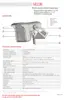
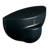
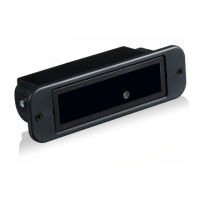
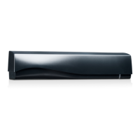
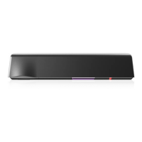
DESCRIPTION OF
THE SENSOR
INSTALLATION
TIPS
TECHNICAL
SPECIFICATIONS