Page 4 of 12 75.5905.06 BODYGUARD-T 20190402
1
3
2
2
1
1
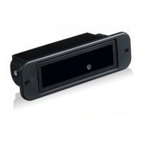
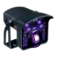
SENSOR INSTALLATION
Align the sensor with the chosen location and attach the sensor
using the two self-drilling screws (provided with kit). A pilot hole
in the header may be necessary to ease screw installation.
If the sensor is mounted directly to the header and the cabling will
pass directly through the header, drill a
1
⁄2" wire passage hole next
to the left-side end cap. Ensure that the hole location aligns with
the end cap cut-out.
Route harness through wire passage hole while aligning the sensor
with the Bodymount.
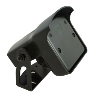
Attach the sensor to the Bodymount using the two self-drilling
screws (provided with the kit).
Slide the circuit board back into the extrusion.
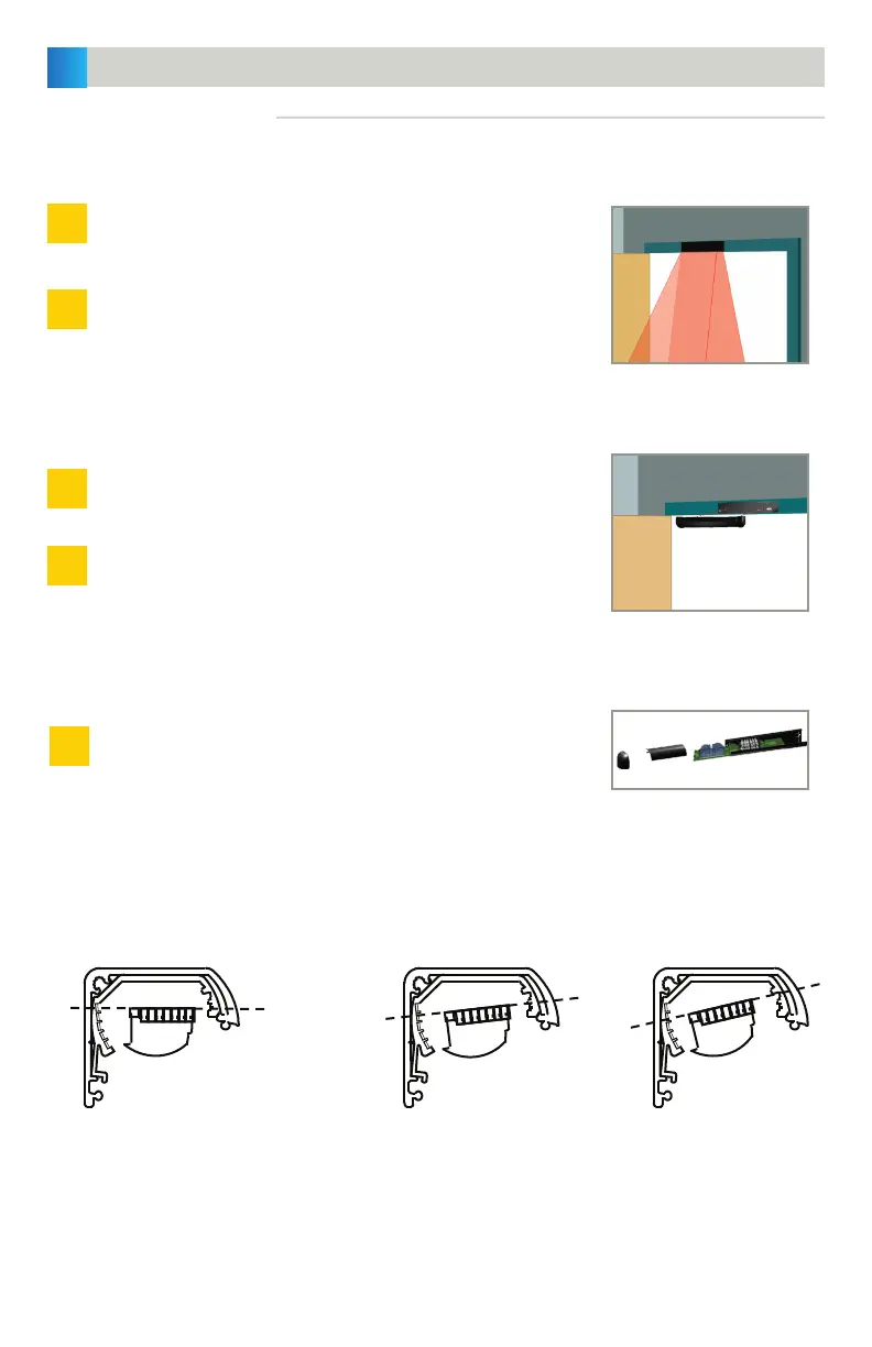
MOUNTING DIRECTLY TO DOOR FRAME/HEADER:
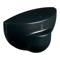
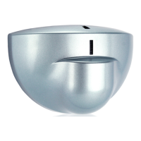
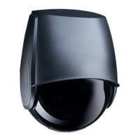
ANGLE ADJUSTMENTS:
MOUNTING TO BODYMOUNT:
REPLACE THE CIRCUIT BOARD:
MECHANICAL INSTALLATION (cont.)
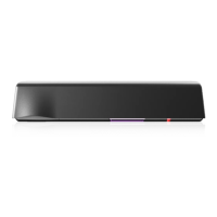
0°
Should only be used when the sensor is
mounted to a Bodymount block or soffit
above the door that extends out from the
face of the safety side of the door. This
would improve the detection field location
across the threshold area of the doorway.
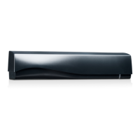
5° (FACTORY DEFAULT)
For most applications, it is recommended
that the unit be powered and walk-tested
at this angle. After walk-testing, the
detection field may be altered by adjusting
the angle (see directions below).
10°
Make any necessary angle adjustments after installation. Use the images below to aid in choosing angles.
Angles must match for each clip on the same PCB.