EasyManua.ls Logo

BEA Superscan User Manual

BEA Superscan
17 pages
To Next Page IconTo Next Page
Page #1 background imageLoading...
Page #1 background image
SUPERSCAN
USER’S GUIDE
PRESENCE SENSOR
DESCRIPTION
The SuperScan (10SSI, 10SSII, 10SSIII) detector is a door-mounted presence detection system that is used on automatic
pedestrian swing doors. The SuperScan can be used on an SMR or non-SMR system. Unlike other door-mounted sensing
devices, the SuperScan's unique electronic architecture allows the detection modules to be mounted near the top of the
door, out of harm's way. A rotating cam is used for the range adjustment of the detection zone. Width patterns may be
altered by adding slave modules to the master module. These slave modules are simply added by inserting them into the
aluminum extrusion, then connecting them with the attached flat ribbon cable to the next module without interrupting other
modules in the same extrusion. Once installed, the detection zone (in addition to being adjustable for distance) can be
angled independently from the other modules.
Each SuperScan module consists of two optics, a transmitter (TX) and a receiver (RX), and functions independently of the
other modules. The transmitter emits an extremely precise beam, which measures approximately 4" in diameter at a
distance of 8'. The receiver, in turn, receives the infrared beam reflected off of the floor. This transmission and reception
forms a detection triangle, which is the basic premise of detection (called triangulation). Should this angle be interrupted,
detection will occur. Detection is NOT based upon the intensity of the beam, and in principle will not be affected by the color
or background of the object that interrupts the angle.
TECHNIC
SPECIFICATIONS
DESCRIPTION SPECIFICATION
Power Supply 12 to 24 VAC ± 10% / 12 to 24 VDC + 10%
Current Consumption:
Master: On = 60 mA max. / Master: Off = 30 mA max.
Slave: On = 40 mA. Max. / Slave: Off = 30 mA max.
Input Inhibit 12 to 24 VAC ± 10%: / 12 to 24 VDC + 10% / Inhibited when voltage is applied
SMR Input Data 12-18 VDC: Inhibited when voltage is applied
Output Interface; relay Relay; max. contact rating is 1A @ 30v ( resistive)
Detection Range 0' to 8'
Distance Adjustment 2’ to 8’ / Rotating cam with linear adjustment
Max. Mounting Height 8’
Detection Time < 50 ms
Detection Signal Duration Infinite Presence Detection
Output Hold Time Potentiometer Range: 0.1 to 4.5 seconds.
LED Indications Master: Red LED = Detection
Green LED = Active Output
Slave: Red LED = Detection
Operating Temperature
Range
-30° F to 140° F
PCB Dimensions Master: 10.91" x 1.5"
Slave: 8.75" x 1.5"
Connection to Door
Controller
8 Position Screw Terminal on Master PCB
Connection: Master to
Slave
Flat Ribbon Cable With Connectors and Key Lock
Max. Number of Slaves Standard = 9 / With Monitoring = 8 max.
Functions Selection Detection Mode - NO or NC
Normal Mode or Background Analysis Mode
75.0084.05 20110720 Page 1 of 17
Shut off all power going to the header before attempting any wiring procedures.
Maintain a clean & safe environment when working in public areas.
Constantly be aware of pedestrian traffic around the door area.
Always stop pedestrian traffic through the doorway when performing tests that may result in unexpected
reactions by the door.
Always check placement of all wiring and components before powering up to ensure that moving door parts
will not catch any wires and cause damage to equipment.
Ensure compliance with all applicable safety standards (i.e. ANSI A156.10, 156.27) upon completion of
installation.
SAFETY
PRECAUTIONS
!
CAUTION
Jamb Hole Cover
SuperScan Assembly
Wire Transfer Sheath
8-Wire Cable

Other manuals for BEA Superscan

Question and Answer IconNeed help?

Do you have a question about the BEA Superscan and is the answer not in the manual?

BEA Superscan Specifications

General IconGeneral
BrandBEA
ModelSuperscan
CategoryAccessories
LanguageEnglish

Summary

DESCRIPTION

Presence Sensor

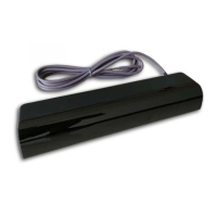
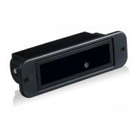
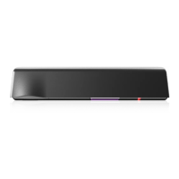
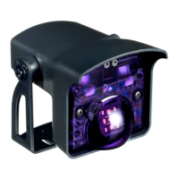
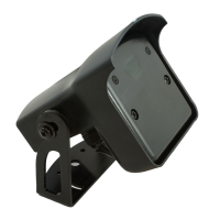
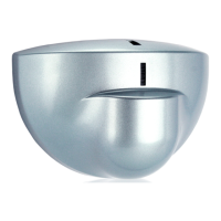
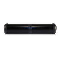
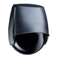
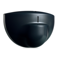
Door-mounted presence detection system for automatic pedestrian swing doors.

TECHNICAL SPECIFICATIONS

Sensor Technical Data

Detailed technical parameters including power, current, input, output, range, and dimensions.

SAFETY PRECAUTIONS

General Safety Advice

Important safety advice and cautions for installation and operation.

INSTALLATION TIPS

Mounting Best Practices

Guidelines for secure sensor mounting, avoiding vibration and interference.

MECHANICAL INSTALLATION

Preparing and Mounting the Sensor

Steps for removing components, preparing the extrusion, and ensuring proper door fitment.

Drilling and Securing the Unit

Instructions for marking, drilling, and attaching the SuperScan extrusion to the door.

Wire Passage and Extension

Procedures for creating wire passage holes and preparing extension wires.

Wire Passage in Header and Jamb

Creating wire passage holes in the door header and jamb tube for cable routing.

ELECTRICAL INSTALLATION

Cabling and Connections

Wiring the terminal connector on the SuperScan master module according to application.

Installing End Caps and Lens

Final steps for installing end caps and the SuperScan lens after wiring.

MECHANICAL ADJUSTMENTS

Jumper Settings

Configuring master and slave board jumpers for mode and function selection.

Relay Mode Configuration

Setting the relay mode (passive or active) using the two-position jumper J2.

SMR Mode and Jumper Settings

Configuring SMR mode using J3 and master/slave configuration using J4.

Hold-Time Adjustment

Adjusting the hold-time potentiometer (P1) for detection duration.

MASTER / SLAVE CONFIGURATION AND COMPATIBILITY LIST

Module Compatibility Table

Table showing compatibility between different master and slave module configurations.

Master Module Configurations

Diagrams of master module jumper settings for various configurations.

Slave Module Configurations

Diagrams of slave module jumper settings for various configurations.

MODULE POSITIONING AND ANGULATION

Module Positioning

Positioning modules within the extrusion, ensuring transmitter is at the leading edge.

Module Angling

Setting the independent angle of each module using provided charts for detection.

POWER-ON ADJUSTMENTS

Inactive Zone Adjustment

Procedures for adjusting detection distance and inactive zone height using a cardboard target.

SMR & NON-SMR COMPATIBILITY

Compatibility Rules

Rules for using SMR and non-SMR modules in the same chain.

TROUBLESHOOTING

Common Problems and Solutions

Identifies common issues, their possible causes, and corrective actions.

ANSI/AAADM COMPLIANCE

Daily Safety Check Guidelines

Requirements for performing daily safety checks and providing owner manuals.

COMPANY CONTACT

BEA Contact Information

Phone numbers and website for customer service and technical support.

ADDENDUM - SCHEMATICS

BESAM 300/400 (ETIK) Control Wiring

Wiring diagram for BESAM 300/400 (ETIK) control with Passport Plus/Parallax 2 system.

BESAM MP VER. 6.3,4 DUAL, LO21B/U Wiring

Wiring diagram for BESAM MP Dual with LO21B/U Passport Plus/Parallax 2 system.

HORTON C4190 CONTROL Wiring

Wiring diagram for Horton C4190 control with Parallax 2 system.

STANLEY MP CONTROL Wiring

Wiring diagram for Stanley MP Control with LO-21P Parallax II system.

Relay Wiring for Stalling/Inhibition

Diagram for wiring a 24-volt isolation relay for SuperScan stall circuit control.

Related product manuals