75.0084.05 20110720 Page 7 of 17
MECHANICAL
ADJUSTMENTS -
PRIOR TO
POWER-ON
Cont.
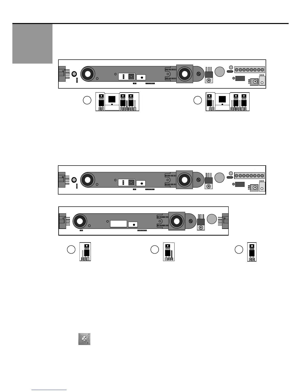
7. Jumper J3 is to toggle the SMR mode on and off, and is located on the master module only.
Jumper installed on both pins = SMR OFF (default setting), Picture 28.
Jumper removed (may be stored on one pin) = SMR ON, Picture 29.
SMR is not available on master modules without jumper J3 installed. See page 8 for module configurations.
29 28
J2
J1
J4
J3
P1
1
J3 J1 J3 J1
SMR ‘OFF’ SMR ‘ON’
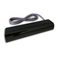
8. Jumper J4, is found on the master module, and is also found on the slave module. On the master module, it determines
‘master only’ or ‘master and slave’ configuration for use when SMR is ON. When the jumper is installed in ‘master only’
configuration, as shown below in picture 30, it is intended for use without slave modules added to the chain and is for ‘master
only’ operation. The jumper is located at the Output end of the master module. With jumper J4 installed as shown in picture
31, the master is intended for slave modules to be added. Jumper J4 is also installed on the slave module near the output end
of the module. SMR is not available on master and slave modules without jumper J4 installed. See page 8 for module
configurations.
Master
Slave
J2
J1
J4
J3
P1
1
J1
J4
4
View Looking Toward
Master Output
30
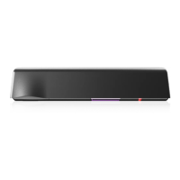
31 32
View Looking Toward
Master Output
4
4
As Shipped From BEA, Inc., default placement of J4 jumpers is as follows:
If a Master ONLY is shipped: Jumper will be positioned for Master Only
If a Slave ONLY is shipped: No jumper on Slave J4 position
If a kit is shipped (i.e. SuperScan II): Jumpers correctly placed for that configuration.
9. On the slave module, jumper J4 should be installed on the last slave module in the chain, as shown above in picture
32. All slave modules between the master and the last slave should have the jumper removed. Latest module
configurations without jumper J4 installed can simply be installed in chain with the master and slaves. See page 8 for
module configurations.
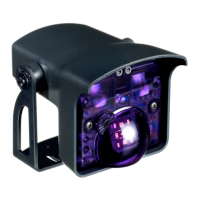
10. There is a hold-time potentiometer (P1) located on the master module. It is located between the receiver and
transmitter. Adjustability ranges from 0.1 to 4.5 seconds. When installed, clockwise rotation increases time
delay.
P1