75.0084.05 20110720 Page 6 of 17
MECHANICAL
ADJUSTMENTS -
PRIOR TO
POWER-ON
Cont.
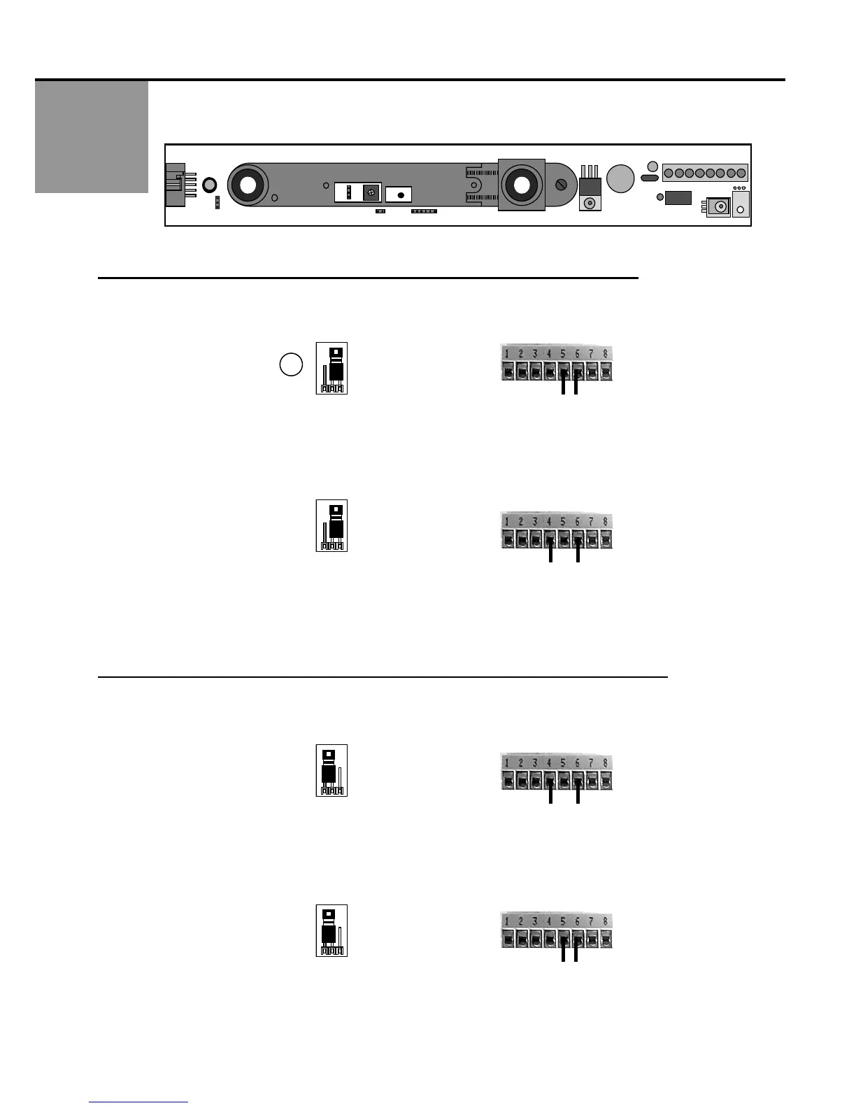
2. J2 is a two-position jumper, which enables either a passive or active relay to be selected. The SuperScan comes
factory preset with the relay in the ACTIVE MODE. J2 IS ON THE MASTER BOARD ONLY.
ACTIVE RELAY: THE RELAY IS ENERGIZED WHEN THE DETECTOR IS AT REST.
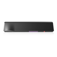
3. ACTIVE RELAY + NC & COM TERMINAL CONNECTION =
CLOSED CONTACT DURING DETECTION
Use the NC & COM terminals (5 & 6) & leave JP2 at the factory preset position.
During detection, led indication will be green led OFF, red led ON.
Upon power loss, the contact will be closed.
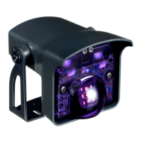
4. ACTIVE RELAY + NO & COM TERMINAL CONNECTION = OPEN CONTACT DURING DETECTION
Use the NO & COM terminals (4 & 6) & leave JP2 at the factory preset position.
During detection, led indication will be green led OFF, red led ON.
Upon power loss, the contact will be open.
PASSIVE RELAY: THE RELAY IS DE-ENERGIZED WHEN THE DETECTOR IS AT REST.
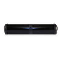
5. PASSIVE RELAY + NO & COM TERMINAL CONNECTION =
CLOSED CONTACT DURING DETECTION
Use NO & COM terminals (4 & 6) & CHANGE JP2 from the factory preset position.
During detection, led indication will be green led ON , red led ON.
Upon power loss, the contact will be open.
6. PASSIVE RELAY + NC & COM TERMINAL CONNECTION = OPEN CONTACT DURING DETECTION
Use the NC & COM terminals (5 & 6) & CHANGE JP2 from the factory preset position.
During detection, led indication will be green led ON, red led ON.
Upon power loss, the contact will be closed.
2
View Looking
Toward P1
2
View Looking
Toward P1
J2
View Looking
Toward P1
2
View Looking
Toward P1
J2
J1
J3
J4
P1
1
27