75.0084.05 20110720 Page 5 of 17
ELECTRICAL
INSTALLATION-
CABLING &
CONNECTIONS
Cont.
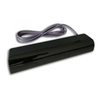
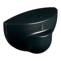
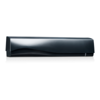
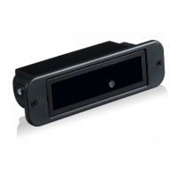
2. Once all wiring has been completed, the end caps and lens may be installed. At the SuperScan end of the cable
(picture 23), leave enough slack to allow a relaxed connection at the terminal block. Locate the Superscan end cap
that goes towards the hinged end of the door. Remove the tab at the bottom of the cap (picture 21) to allow insertion of
the plastic sheath. Insert the plastic sheath (picture 22) and install the end cap. The SuperScan lens may then be
installed to fit tight against the end cap and plastic sheath to hold it in place, as shown in picture 24. Leave the end cap
off at the opposite end until all mechanical adjustments have been completed.
* Refer to the back of this Guide for various wiring schematics.
24 23 22 21
MECHANICAL
ADJUSTMENTS -
PRIOR TO
POWER-ON
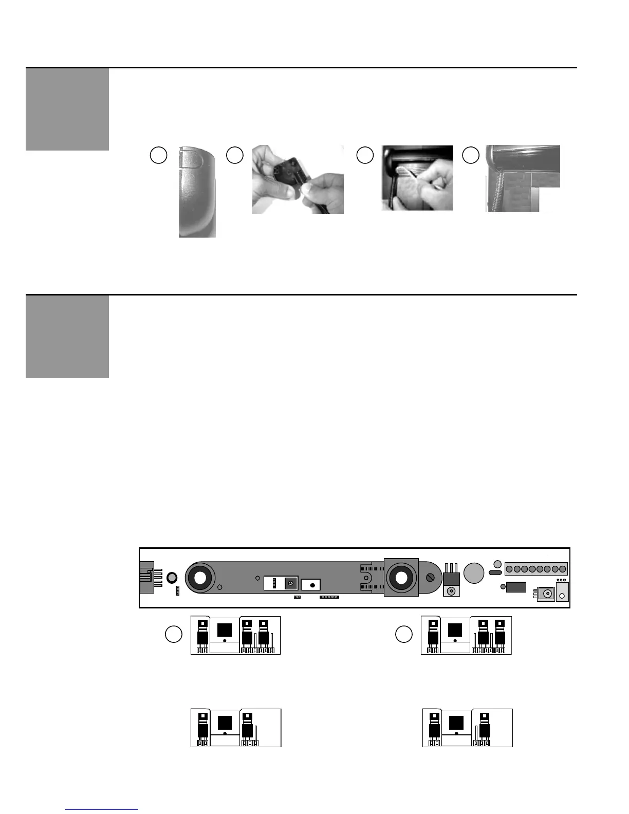
Master & Slave Module Jumper Settings: Prior to power-on, all jumper settings on the master and slave boards should
be set according to the installation.
Jumper settings include:
Function J1: Background Analysis (master & slave boards)
Function J2: Relay Mode (NO / NC) (master board only)
Function J3: SMR Mode (master & slave boards)
Function J4: Master Only or Master & Slave Configuration (master & slave boards)
1. Jumper J1, Background Analysis, is a 6-pin (older models) OR 3-pin (newer models) configuration located on each module,
as shown below in picture 25 - the location is the same for each. Background Analysis is the ability to analyze the
background in the area of the detection field, to help reduce chances of non-detection due to faulty environmental situations.
When ON (picture 26), Background Analysis allows constant detection in the event of one or more of the following situations:
Module aimed too high
Module incorrectly oriented (towards sky for example)
Defective amplification chain
Faulty infrared transmitter
Not enough reflectivity off of floor surface
NOTE: Floor must have at least 5% reflectivity to allow Background Analysis to function properly.
This configuration greatly reduces the chance of allowing the modules to function less than optimally. If one of the above-
stated faults exists, the detector will remain active, thereby causing the door to stay open or to not open. This fail-safe
operation will cause the door to be inoperative in the automatic mode, since there will be a constant signal either to the
safety input or to the activation input of the door control, depending on which module is sensing detection. If an extreme IR
absorbent floor is present, set J1 to background analysis mode. The J1 function must be set on each module.
J2
J1
J4
J3
P1
1
6-Pin
Background
Analysis Mode
6-Pin
Normal Mode
Default
25
26
Newer Models – 3 Pin Jumper – Shown with same orientation as 6-pin jumper above
The same logic applies as with the 6-pin: Center and left pin are for Normal Mode, center and right pin are for
Background Analysis Mode.
3-Pin
Normal Mode
Default
3-Pin
Background
Analysis Mode
J3
1
J1
J3 J1 J3 J1

 Loading...