75.0084.05 20110720 Page 4 of 17
MECHANICAL
INSTALLATION-
PREPARING AND
MOUNTING THE
SENSOR – Cont.
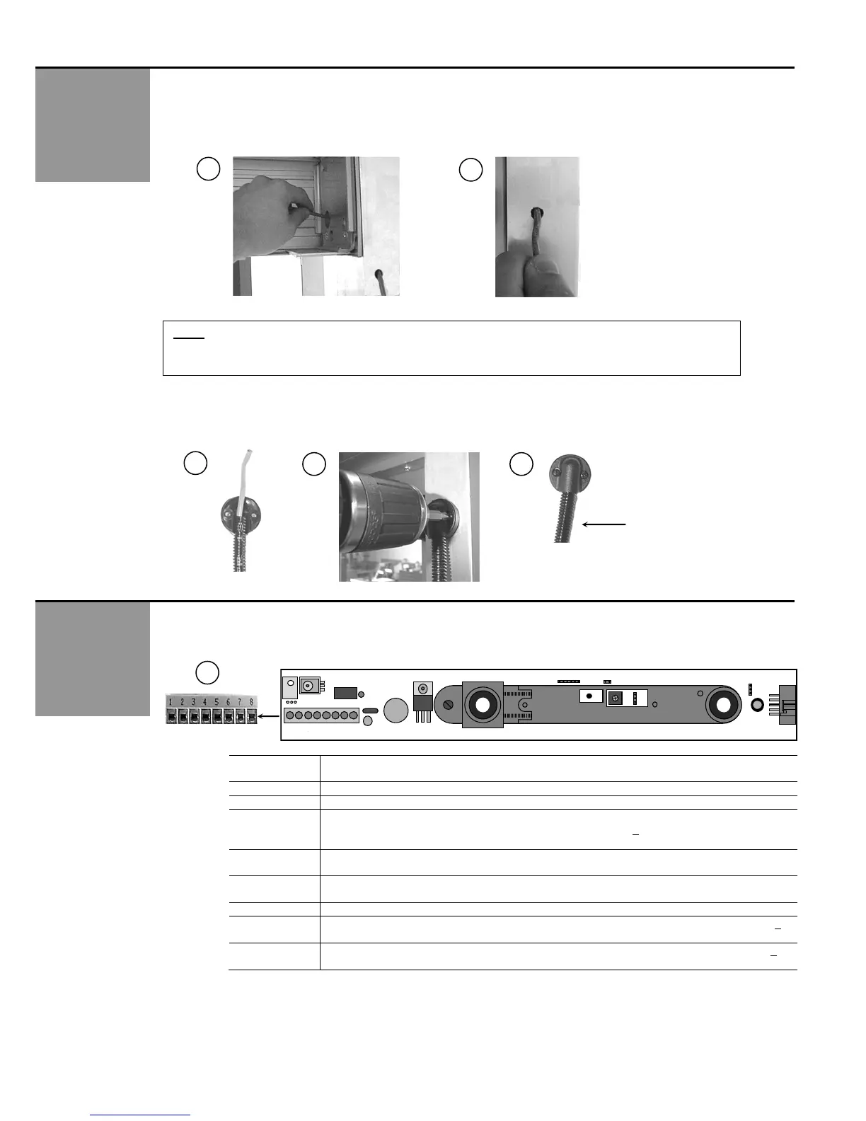
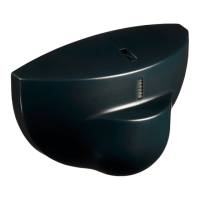
8. Next, a wire passage hole will be required in the door header (Picture 15) and also in the jamb tube (Picture 16) at
approximately the same height as the SuperScan. The wire transfer hole in the jamb should be at the secure side of
the door. Normally this would be the interior side. Feed the wire through the jamb tube up to the header. Insure that
enough wire is left out to reach the SuperScan terminal block.
16
ELECTRICAL
INSTALLATION-
CABLING &
CONNECTIONS
15
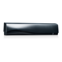
9. Once all cabling is in place, the plastic sheath must be installed over the wire coming out of the jamb tube. This must
be done before making final connection to the terminal block. The sheath may have to be cut to fit the application.
Once the wire is fed though, the plastic cap may be installed on the jamb, over the transfer hole.
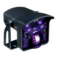
1. With cabling in place, wiring at the terminal connector on the SuperScan master module (picture 20) may be
completed. Wiring will vary according to the application. Available positions on the connector are shown below:
SuperScan
Terminal
Explanation of Wiring Connections
1 Test data - used with SMR systems only.
2 Ground. Negative terminal if Input inhibition is used.
3 Input inhibition: All detection is ignored. Infrared emission is stopped.
Inhibition occurs when 12 to 24 VAC ± 10% or 12 to 24 VDC +
10% is applied between
terminal 3 and terminal 2.
4 (NO) JP2 factory default will close the relay contact on terminal 4 when the SuperScan is
energized and not in detection. Loss of power results in a N.O. contact
5 (NC) JP2 factory default will open the relay contact on terminal 5 when the SuperScan is
energized and not in detection. Loss of power will result in a N.C. contact.
6 (COM) Common contact for relay.
7 (-) This terminal is used for power input. A voltage of 12 to 24 VAC ± 10% or 12 to 24 VDC +
10% must be supplied.
8 (+) This terminal is used for power input. A voltage of 12 to 24 VAC ± 10% or 12 to 24 VDC +
10% must be supplied.
20
19 18
17
Plastic ribbed sheath
J2
J1
J4
J3
P1
1
NOTE: Ensure there is enough slack in cabling to allow adequate movement of the cable throughout the range
of door travel.