75.0084.05 20110720 Page 11 of 17
SMR & NON-SMR
COMPATIBILITY
When using SMR (self-monitoring ready) and non-SMR modules in the same chain, observe the following rules:
Mon-SMR Master modules can NOT be used with SMR Slave modules.
All other combinations will work. However, for a system to function as SMR, all modules must be SMR
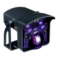
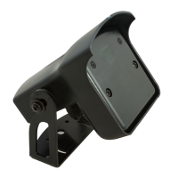
Identifying an SMR module can be accomplished by looking at the white label on the emitter side of the module. Observe the
following to identify each module:
SMR NON-SMR
MASTER EYETECH / MRC EYETECH / MR
SLAVE EYETECH / SC EYETECH / S
For example, a Master module with the marking: EYETECH/MRC would indicate that the module is SMR.
TROUBLE-
SHOOTING
ACCESSORIES
PROBLEM POSSIBLE CAUSE CORRECTIVE ACTION
SuperScan does not work
at all. No LED indications.
Faulty power supply
Faulty connections
Power supply must be 12 to 24 VAC ± 10% or
12 to 24 VDC +
10%.
Check for this power at terminals 7 & 8 of the
affected SuperScan module.
SuperScan output appears to
be working opposite of what is
expected.
Relay output may be configured
improperly.
Refer to page 8 for relay configurations. Be
sure to observe the LED indications on the
affected modules to help determine status.
Door stops by itself before
reaching the full open position.
Safety side SuperScan may be
seeing an adjacent wall or rail
behind the door near the open
position.
Observe the LED status on safety side of
door. Find the SuperScan module that is
falsely being triggered. Check for:
Proper detection angle
Detection range adjustment
SuperScan may need to be inhibited at a
specific point of door travel at the safety side
for proper operation. Refer to the terminal
connections on page 4.
Activation or safety is being
held triggered.
SuperScan detection module may
be seeing the floor or unwanted
object near door.
Reduce the detection range on the affected
module(s). Detection should occur at 12” to
16” above the floor. Refer to page 11.
Erratic detection behavior is
occurring throughout the door’s
opening and closing cycle.
Possible faulty wiring at door
transfer location.
Check each wire for continuity with as multi-
meter, at the transfer location. Move the
wires around during testing to help locate
any breaks. Replace faulty wiring as
necessary.
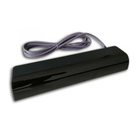
PN: 10REL24V
Isolation Rela
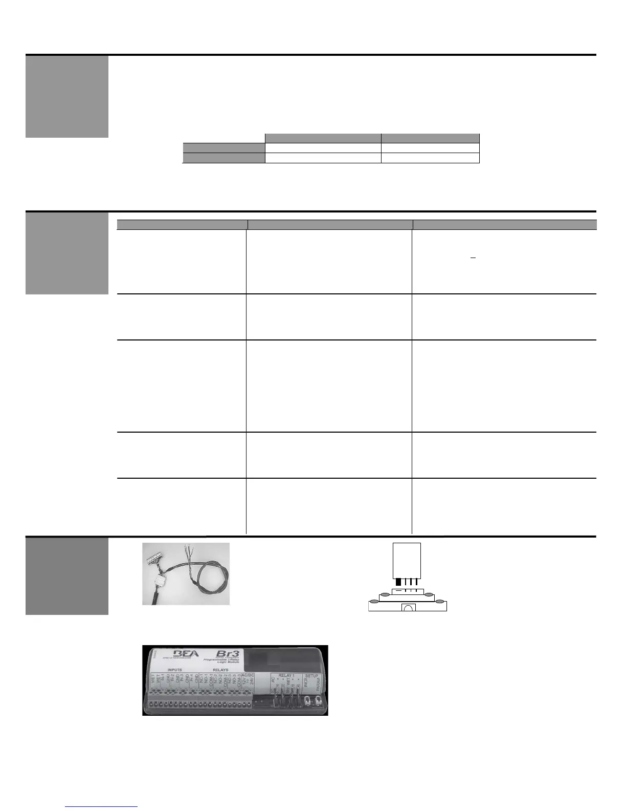
PN: 10SSQD
Quick Disconnect
Cable
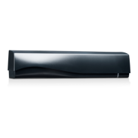
PN: 10BR3
Interface module