75.5905.06 BODYGUARD-T 20190402 Page 5 of 12
2
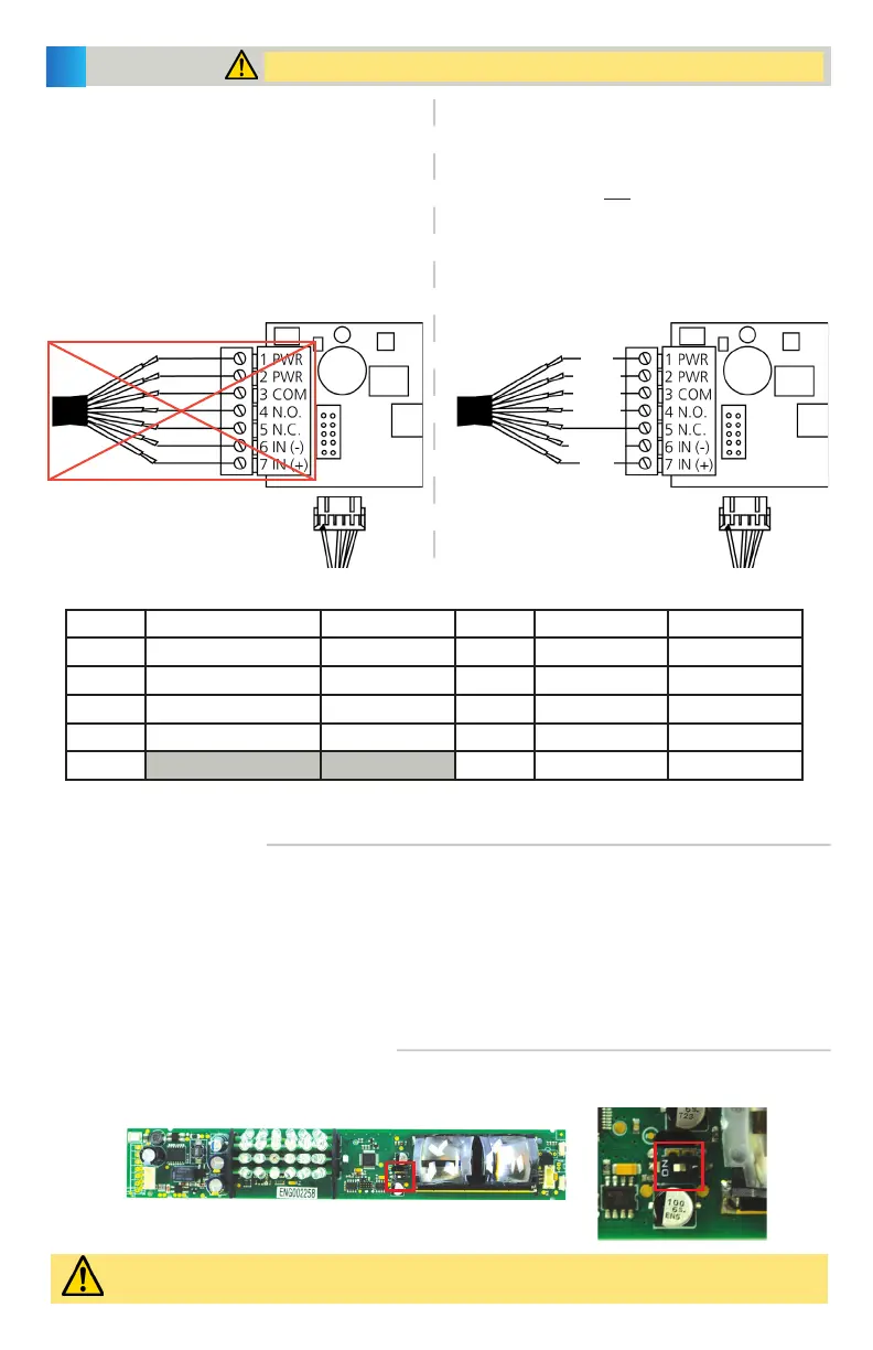
WIRING TO MONITORED DOOR CONTROLS
WIRING TO NON-MONITORED DOOR CONTROLS
WIRING
Shut off all power going to the header before attempting any wiring procedures.
1. Plug the 10-pin connector to the Bodyguard-T
using the provided cable. DO NOT USE the 7-pin
terminal – this is not designed to be used with
monitored systems.
Also verify that the monitoring DIP switch is set to
ON.
2. Hard-wire to the door control. Reference the table
below for connection points.
1. Plug the 10-pin connector to the Bodyguard-T
using the provided cable (without terminating the
monitoring wires) OR hard-wire using the 7-pin
terminal.
Also verify that the monitoring DIP switch is set to
OFF.
2. Hard-wire to the door control. Reference the table
below for connection points.
10-PIN CONNECTOR (hard-wire connections)
Position Connection Wire Color Position Connection Wire Color
1 12 – 24 VAC/VDC ±10% BLACK 6 Normally Closed YELLOW
2 12 – 24 VAC/VDC ±10% RED 7 Monitoring (+) PURPLE/YELLOW
3 Common WHITE 8 Monitoring (-) PURPLE
4 Normally Open GREEN 9 Data (+) BLUE
5 10 Data (-) BROWN
WIRING TO MODULES
MONITORING DIP SWITCH POSITION
Replace lenses, eye shield, and end caps before proceeding.
If wiring the Bodyguard-T to a BEA module (e.g. LO21, MC15), refer to the respective schematic for the module.
Monitoring may not be used if wiring to a BEA module; therefore, the DIP switch must be switched off.
Once wired, feed the free end of the cable through the wire passage hole (page 3, step 8), and into the header.
Pull the cable completely through and route it to the location of the automatic door control.
Refer to the respective User’s Guide for the BEA product with which you are interfacing.
Ensure a dedicated power source of 12 or 24 VAC / VDC ±10% (1024VAC may be used for powering this product).
The monitoring DIP switch is in the ON position by default. This must be placed in the OFF position if the
door control does not support monitoring.
Monitoring OFF = switch positioned to the right
Monitoring ON = switch positioned to the left
RED
BLACK
WHITE
GREEN
BROWN
BLUE