Pin Pin Name Pin Description Source Destination Recommen
-
ded cable
type
23 Illumination B Illumination control Aircraft illumination
voltage
AWG24
24 Not connected — — — —
25 GND Ground, additionally
connected to pin 13
Aircraft DC supply
ground
BXP6401-X-(XX) AWG20
*NOTE:
If parallel altimeter and GPS receiver is not used then pin 2 serves as GPS Enable/Dis
-
able input (active LOW) should be left not connected.
**NOTE:
See Fig. 2.6 for RS-232 GPS receiver connection details.
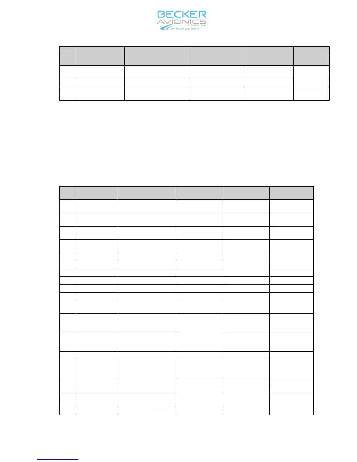
D. Pin connections of the unit connector J8
The unit connector type is D-SUB 25-pins female.
Pin
Pin Name Pin Description Source Destination Recommended
cable type
1 Not connected Reserved for protocol
selection
— — —
2 GPS_EN GPS /Enable Aircraft DC supp-
ly ground*
BXP6401-X-(XX) AWG 26
3 GND Ground connection Aircraft DC supp-
ly ground
BXP6401-X-(XX) AWG 24
4 BSUPP BE6400 blind encoder
supply**
BXP 6401-X-(XX) BE6400 —
5 Not connected — — — —
6 Not connected — — — —
7 Not connected — — — —
8 Not connected — — — —
9 Not connected — — — —
10 Not connected Reserved for SQ — — —
11 GND SWITCH “Weight-on-wheels”
sensor, active LOW
Aircraft BXP6401-X-(XX) AWG 26
12
13
ALTS-
ALTS+
RS-422 data interfa
-
ce***
Serial encoding
altimeter
BXP6401-X-(XX) 2 x AWG26 twi
-
sted pair, shiel
-
ded
14
15
TISRX-
TISRX+
RS-422 data interface ADLP BXP6401-X-(XX) 2 x AWG26 twi
-
sted pair, shiel
-
ded
16 Not connected — — — —
17
18
TISTX-
TISTX+
RS-422 data interface BXP6401-X-(XX) ADLP 2 x AWG26 twi
-
sted pair, shiel
-
ded
19 Not connected — — — —
20 Not connected — — — —
21 GND Ground connection Aircraft DC supp
-
ly ground
BXP6401-X-(XX) AWG 24
22 Not connected — — — —
Page 2-3
34-50-08 September 2011
INSTALLATION AND OPERATION BXP6401-X-(XX)
 Loading...