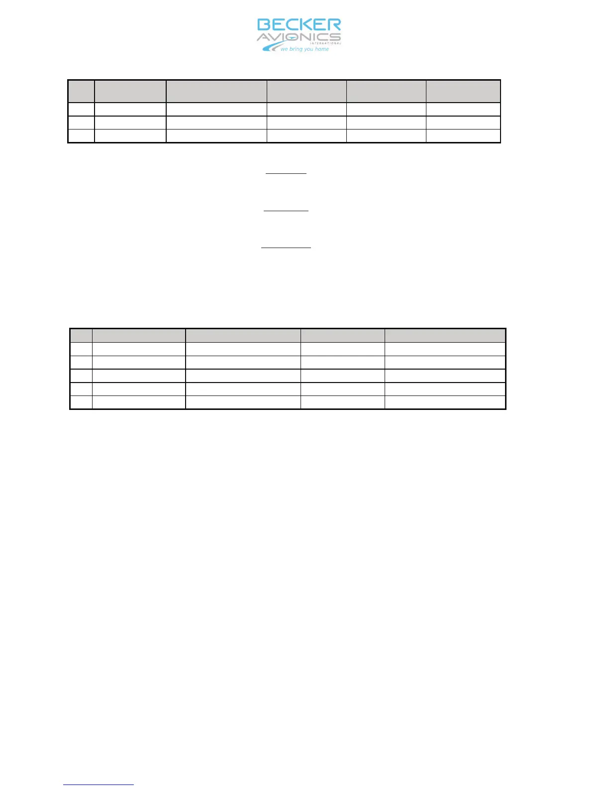
Pin
Pin Name Pin Description Source Destination Recommended
cable type
23 Not connected — — — —
24 Not connected — — — —
25 Not connected — — — —
* NOTE:
If GPS receiver is not used pin 2 should be left not connected.
** NOTE:
Do not connect if BE6400 is not used.
*** NOTE:
See Fig. 2-3 for RS-232 serial encoding altimeter connection details.
E. Pin connections of the unit connector J7
The unit connector type is subminature 5-pins female.
Pin
Pin Name Pin Description Source Destination
1 VCC Power supply BXP6401-X-(XX) AM6400-1-(01)
2 I2C_CLK Bus clock AM6400-1-(01) BXP6401-X-(XX)
3 Not connected Reserved — —
4 I2C_DAT Bus data AM6400-1-(01) BXP6401-X-(XX)
05 GND Supply GND BXP6401-X-(XX) AM6400-1-(01)
F. DME suppression
If required, connect the suppression in/out of transponder to the correspon
-
ding pin of the DME unit or any relevant device.
G. External IDENT push-button
If this input (Pin 4 of unit connector P9) is briefly connected to GND (e.g. by
an external push-button), the IDENT function (SPI) is started in the same way
as when using the IDENT push-button on the front panel.
H. Ground switch
If required, connect an automatic ground switch (weight on wheel sensor) at
Pin 11 of unit connector J8.
I. Illumination
For external illumination control connect the illumination voltage to pin 10 of
P 9 and attach pin 23 to the illumination ground. Set the max. illumination
voltage in the installation menu. For manual illumination control set dimming
input to “none” in the installation menu. Set illumination intensity manually in
the configuration menu.
INSTALLATION AND OPERATION BXP6401-X-(XX)
Page 2-4
34-50-08 September 2011
 Loading...