Beckett
Instruction Manual – Model NX Oil Burne
Prepare burner
Install burner nozzle (if not already installed)
(continued)
Low Firing Rate Baffle
Use care when removing and installing oil nozzles:
The NX Low Firing Rate Baffle (LFRB), item 25, page 11, reduces the burner
air flow and pressure. The LFRB is sometimes used for firing rates under
1.10 GPH. Refer to the appliance manufacturer’s instructions or the Beckett
OEM Specification Guide part number 6711. Do not omit the LFRB when
specified. Omitting the baffle when specified or installing the baffle when not
specified could result in poor burner performance.
• Inspect the nozzle adapter before installing nozzle. If it is grooved or
scratched on the sealing surface, replace the nozzle line assembly.
Otherwise, oil could leak at the nozzle-adapter joint, causing serious
combustion problems.
•
Protect the nozzle orifice and strainer when installing. If the orifice gets
dirt in it or is scratched, the nozzle will not function properly.
Burner fuel unit
•
Do not over-torque the nozzle when installing. This will cause deep
grooves in the nozzle adapter, preventing a seal when a new nozzle is
installed.
• Verify that the burner fuel unit is compatible with the oil supply system. For
more details, refer to “Connect fuel lines” on page 8.
Attach air tube (if not already installed)
•
Use a wrench to hold the nozzle adapter.
DO NOT
attempt to remove or
replace nozzle without holding adapter. The nozzle alignment could be
seriously damaged. Use a nozzle wrench that secures the adapter or
use
3
/
4
" and
5
/
8
" open-end wrenches.
If using an adjustable flange and gasket, slide them onto the air tube. Then
attach the air tube to the burner chassis using the four sheet metal screws
provided.
•
Do not squeeze the electrodes too tightly when handling the nozzle line
assembly. This could change the electrode tip settings or damage the
ceramic electrode insulators.
Install burner nozzle (if not already installed)
Make certain the correct nozzle is selected for the actual fuel
unit pressure. Nozzles are rated for 100 psig operation. With standard NX fuel
unit pressure of 140 psig, the nozzle rated capacity will be lower than the
appliance firing rate. See Table 3. Use only the specified spray pattern unless
combustion test results indicate the need for a change. Failure to use the
correct nozzle size and type can result in unacceptable combustion, possibly
causing severe personal injury, death or substantial property damage.
1. Remove the plastic plug protecting the nozzle adapter threads
2. Place a ¾” open-end wrench on the nozzle adapter. Insert the nozzle into
the adapter and finger tighten. Finish tightening with a ⅝” open-end
wrench. Use care to avoid bending the burner head support legs or
electrodes. See CAUTION, above right.
3. If you remove the head to replace the nozzle, carefully reconnect the head
to the nozzle adapter, making sure to align the key in the support leg with
the keyway in the nozzle adapter and to butt the head support to the
nozzle adapter shoulder (see Figure 2, page 6).
If the nozzle is already installed, remove the nozzle line assembly to verify that
the nozzle size and spray pattern are correct for the application (per appliance
manufacturer’s information or Beckett
OEM Specification Guide,
part number
6711. Verify that the electrode tip settings comply with Figure 1, page 6.
If the nozzle is not installed, obtain a nozzle of the manufacturer, capacity and
spray angle specified in appliance manufacturer’s information or Beckett
OEM
Specification Guide. For conversions or upgrades, when information is not
available for the application:
4. Refer to table below to select the mid-range nozzle spray angle for the
head type being used.
5. Fire the burner and make sure the combustion is acceptable and the
flame is not impinging on chamber surfaces.
6. If a shorter flame is needed, select a wider spray angle. If a longer flame
is needed, select a narrower spray angle.
7. Either hollow or solid spray patterns may be used. If combustion results
are not satisfactory with the selected spray pattern, try the other pattern.
•
Carefully check and realign electrode tips after replacing nozzle,
ensuring the electrode settings comply with Figure 1, page 6.
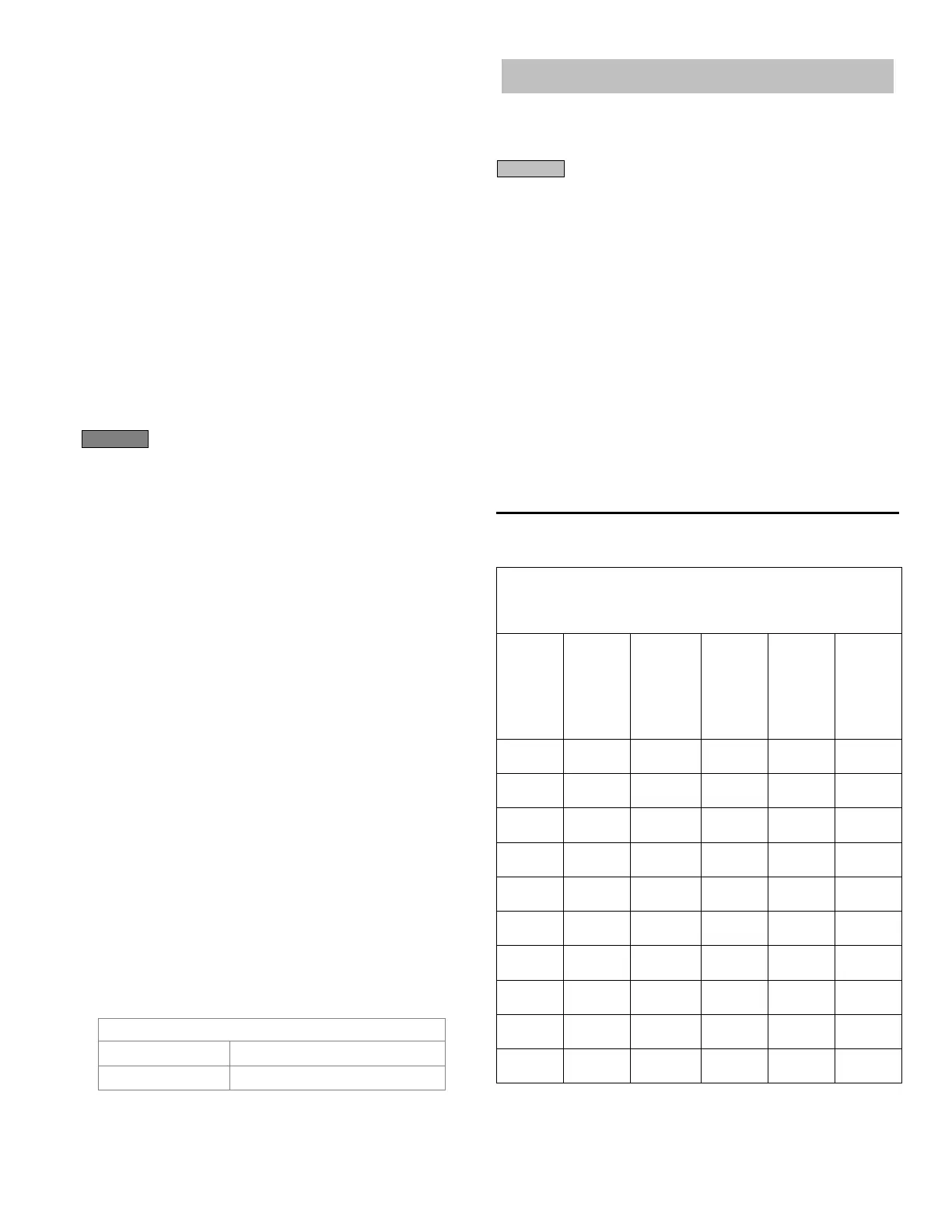
Table 3
– Nozzle size / pressure
Nozzle flow rate
U. S. gallons per hour of No. 2 fuel oil
when pump pressure (psig) is:
Nozzle
size
(rated at
100
psig)
125
140
(factory
std.)
150 175 200
0.40 0.45 0.47 0.49 0.53 0.56
0.50 0.56 0.59 0.61 0.66 0.71
0.60 0.67 0.71 0.74 0.79 0.85
0.65 0.73 0.77 0.80 0.86 0.92
0.75 0.84 0.89 0.92 0.99 1.06
0.85 0.95 1.01 1.04 1.13 1.20
0.90 1.01 1.07 1.10 1.19 1.27
1.00 1.12 1.18 1.23 1.32 1.41
1.10 1.23 1.30 1.35 1.46 1.56
1.20 1.34 1.42 1.47 1.59 1.70
CAUTION
Prepare burner & site
WARNING
Recommended nozzle spray angles
6-slot head 45°, 60°, or 70° nozzle
9-slot head 45°, 60°, or 70° nozzle
5
 Loading...