Instruction Manual – Model NX Oil Burner
Beckett
Prepare burner & site
Check/adjust “Zero” calibration
Prepare burner
(continued)
1. See Figure 3. The zero calibration has been factory set on burners
with factory-installed air tubes. Make sure the retention head is
securely against the stops in the retention ring when the
adjustment plate pointer is at “0”.
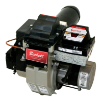
Check/adjust electrodes
Check the electrode tip settings. Adjust if necessary to comply with the
dimensions shown in Figure 1. To adjust, loosen the electrode clamp screw
and slide/rotate electrodes as necessary. Securely tighten the clamp screw
when finished.
2. If the zero calibration has not been set, use the following procedure
to adjust:
•
Install the nozzle line assembly with the adjustment plate
assembly into the burner.
Figure 1
– Electrode tip gap and spacing
•
Install and tighten the rear door to hold the air adjustment
plate assembly in position.
•
Slightly loosen the top left acorn nut, splined nut, and lower
acorn nut.
•
Set the plate with the pointer to the zero position by turning
the air adjustment screw clockwise.
•
Slide the nozzle line assembly forward until the retention
head engages the fixed stops in the retention ring at the end
of the air tube. See Figure 4, page 7.
•
Tighten the top left acorn nut securely.
Servicing nozzle line assembly
3. The rear door must be kept tightly closed. The adjustment screw
may now be turned to adjust the head/air setting. Tighten the
splined nut and lower acorn nut after head/air setting has been
made.
1. Turn off power to burner before proceeding.
2. Remove burner cover by loosening the four thumb screws (two on each
side of burner).
3. Disconnect copper oil connector tube from nozzle line.
4. Loosen the two screws securing igniter retaining clips and rotate both clips
to release the igniter baseplate. The igniter should pop up and be
supported by the prop spring.
5. Loosen the two screws securing the rear door. Swing door to the right
and down
6. Loosen splined nut.
7. Remove nozzle line assembly from burner by drawing it straight back out
the rear door opening. Be careful not to damage the electrodes or
insulators while handling.
8. To replace the nozzle assembly, reverse the above steps.
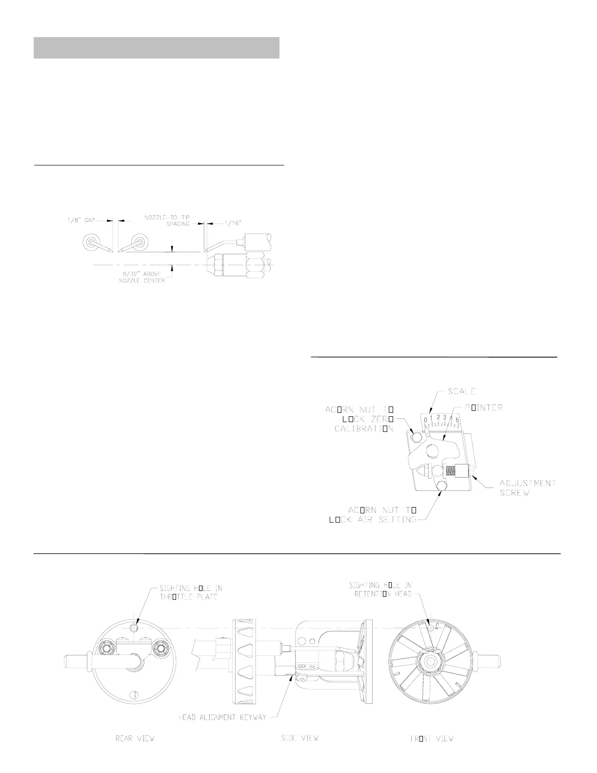
Check retention head alignment
See Figure 2. Cad cell sighting holes in the throttle plate and retention head
must line up so the cad cell can see the flame. Make sure the “key” in the
retention head leg lines up with the “keyway” in the nozzle adapter when
mounting the retention head.
6
Figure 2
– Retention head/throttle plate alignment
Figure 3
– Head/air adjustment plate assembly
SK9665
SK9667
Side view End view
SK9664
 Loading...