Beckett
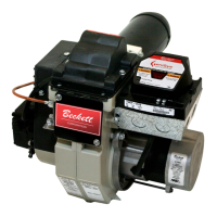
Instruction Manual – Model NX Oil Burne
Adjust, pipe, & wire burne
Wire burner
Covered burners
Burner packaged with appliance
The cover mounting plate is not a conduit connection point. Pass
conduit and attached connector through the front opening in the
mounting plate or through one of the knockouts on either side of the
cover and attach it directly to the burner-mounted 4x4 electrical box.
• Refer to appliance manufacturer’s wiring diagram for electrical connections.
Burner applied at jobsite
• Refer to Figure 6, page 9, for typical burner wiring, showing cad cell
primary controls. Burner wiring may vary, depending on primary control
actually used. The oil valve shown in Figure 6 is the typical arrangement
for NX burners.
All wiring must be in accordance with the latest revision of
National Electric Code
NFPA 70 and local codes and regulations.
The wiring diagrams in this manual are for general reference
only, and apply only to burners equipped with R7184 primary controls. For
other controls, refer to the control manufacturer’s literature or the diagrams
supplied with the appliance. Failure to apply correct wiring could result in
severe personal injury, death or substantial property damage.
The
R7184
primary control with valve-on delay (
prepurge
) and
burner motor-off delay (postpurge), shown in Figure 6, page 9, requires a
constant 120 Vac power source supplied to the BLACK wire on the control.
The RED wire goes to the appliance limit circuit. Please note that other control
manufacturers may use different wire colors for power and limit connections.
SK9669
NOTICE
WARNING
NOTICE
Table 5
– R7184 primary control features
Figure 6
– Typical wiring, R7184 primary control (R7184P shown)
Electrical shock hazard. Disconnect
power before servicing.
DANGER
SK9359
FEATURE R7184B R7184P
Interrupted ignition YES YES
Limited reset, limited recycle YES YES
Diagnostic LED, cad cell indicator YES YES
Valve-on delay YES YES
Burner motor-off delay YES
Alarm contacts Optional
9
 Loading...