10
Section: MOUNT BURNER ON APPLIANCE
Installing the Oil Tank and Supply System
Oil Leak and Fire
Hazard
Install the oil tank following applicable standards
in the U.S. by referring to the latest edition of
NFPA 31 or CSA-B139 & CSA-B140 in Canada, and
all authorities having jurisdiction.
Do Not Use Teon Tape
Damage to the pump could cause impaired burner
operation, oil leakage and appliance soot-up.
y Never use Teon tape on fuel oil ttings.
y Tape fragments can lodge in fuel line components
and fuel unit, damaging the equipment and preventing
proper operation.
y Use oil-resistant pipe sealant compounds.
Note: to determine the proper fuel line size, refer to the
fuel pump manufacturer’s instructions provided with
the burner. Refer to Figure 6 or Figure 7 for typical
installation layouts.
To further protect the fuel supply
system and reduce nozzle orice
plugging, a dual ltration system can be installed.
This typically consists of a 50 micron primary lter,
located near the fuel tank and a secondary lter rated
for at least 10 microns located near the burner.
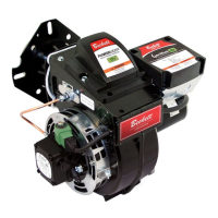
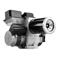
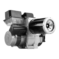
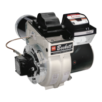
Figure 5 – Mounting Burner in Appliance
Connect Fuel Lines
Carefully follow the fuel unit manufacturer’s literature
and the latest edition of NFPA 31 for oil supply system
specications (CSA B-139 in Canada).
Fuel supply level with or above burner –
The burner may be equipped with a single-stage fuel
unit for these installations. Connect the fuel supply to the
burner with a single supply line if you want a one-pipe
system (making sure the bypass plug is NOT installed in
the fuel unit.) Manual bleeding of the fuel unit is required
on initial start-up. If connecting a two-pipe fuel supply,
install the fuel unit bypass plug.
Figure 6 – Inside Tank Gravity Feed System
Figure 7 – Outside Buried Tank-Lift System
SK8745
Tilt down 2°
If space between burner air
tube and opening exceeds 1/2
inch, pack burner opening with
ceramic ber refractory.
4”
1/4”
A
7/8”
 Loading...