13
SF/SM Burner Manual
Section: BURNER CONTROLS
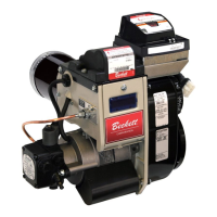
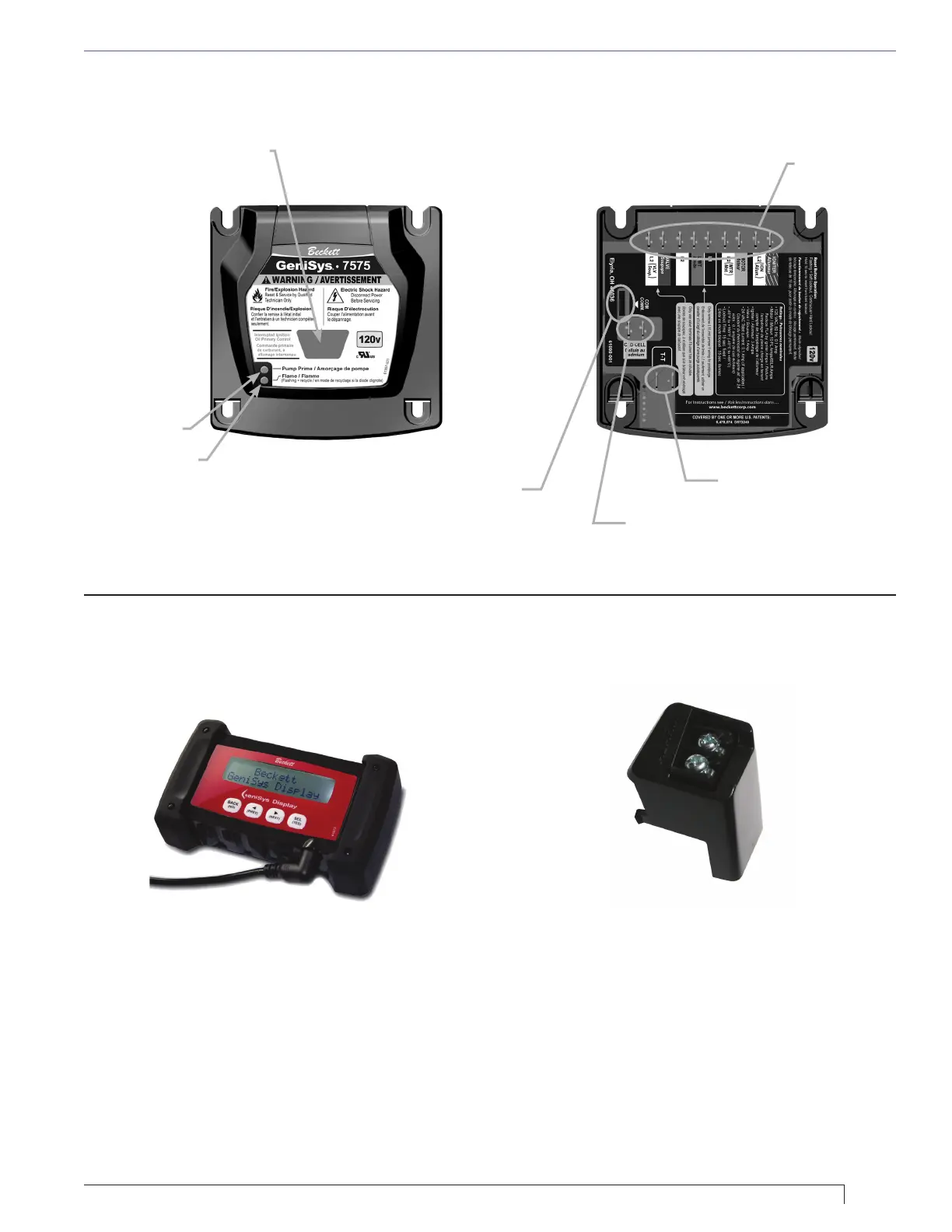
Figure 8B – 7575 Control (all connections are located on the bottom of the control.)
Contractor’s Tool: Hand-held device
for programming and diagnostics
Alarm Module: For adding isolated low voltage
alarm contacts to the base control. See Alarm
Module Instructions for specications.
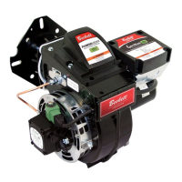
Figure 8C – Optional Components:
Reset Button with Red Light
Green Light
Yellow Light
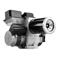
Thermostat
Terminals
Wiring
Connections
Cad Cell
Connections
Communication
Port
 Loading...