List of illustrations
BC8050 und BC815092 Version: 3.0.0
List of illustrations
Fig. 1 The principle of the Bus Terminal ................................................................................................ 9
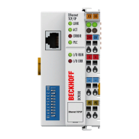
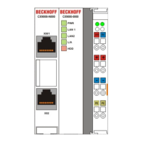
Fig. 2 BC8050........................................................................................................................................ 13
Fig. 3 BC8150........................................................................................................................................ 14
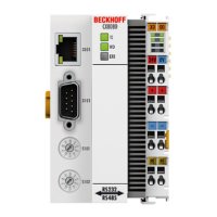
Fig. 4 BCxx50 ........................................................................................................................................ 16
Fig. 5 Release the locking mechanism by pulling the orange tab.......................................................... 17
Fig. 6 Power contact on the left ............................................................................................................. 17
Fig. 7 Potential groups of a Bus Terminal block .................................................................................... 18
Fig. 8 Power contact on the left ............................................................................................................. 19
Fig. 9 Terminal points for the Bus Terminal Controller supply............................................................... 20
Fig. 10 UL identification ........................................................................................................................... 20
Fig. 11 Programming cable KS2000-Z2 .................................................................................................. 21
Fig. 12 RS232 pin assignment................................................................................................................. 22
Fig. 13 Three-core cable with shield, crossed ......................................................................................... 22
Fig. 14 RS485 pin assignment................................................................................................................. 23
Fig. 15 Two-core cable with shield .......................................................................................................... 23
Fig. 16 Start-up behavior of the Bus Terminal Controller ........................................................................ 24
Fig. 17 Setting the node ID ...................................................................................................................... 25
Fig. 18 Creating a TwinCAT configuration............................................................................................... 28
Fig. 19 Selecting the Bus Terminal Controller ......................................................................................... 28
Fig. 20 Downloading a TwinCAT configuration........................................................................................ 29
Fig. 21 Selecting the Bus Terminal Controller ......................................................................................... 29
Fig. 22 State of the Bus Terminal Controller............................................................................................ 29
Fig. 23 Activating the TwinCAT configuration.......................................................................................... 30
Fig. 24 Choose Target System ................................................................................................................ 31
Fig. 25 Selecting the Bus Terminal Controller ......................................................................................... 31
Fig. 26 State of the Bus Terminal Controller............................................................................................ 31
Fig. 27 Uploading the TwinCAT configuration ......................................................................................... 32
Fig. 28 Memory for code mapping ........................................................................................................... 32
Fig. 29 Data memory mapping ................................................................................................................ 33
Fig. 30 Code and data memory ............................................................................................................... 33
Fig. 31 Other memory.............................................................................................................................. 34
Fig. 32 Properties of the remote connection............................................................................................ 35
Fig. 33 Selection dialog "New from Template" ....................................................................................... 36
Fig. 34 Selection of Bus Controller ......................................................................................................... 36
Fig. 35 "Communication Properties" tab.................................................................................................. 37
Fig. 36 Creating variables (inputs, outputs) ............................................................................................. 37
Fig. 37 Definition of variables ................................................................................................................. 37
Fig. 38 BX Settings tab ............................................................................................................................ 38
Fig. 39 BX Diag tab.................................................................................................................................. 39
Fig. 40 Maximum number of POUs exceeded......................................................................................... 42
Fig. 41 Menu path Projects / Options / Controller Settings...................................................................... 42
Fig. 42 Controller settings........................................................................................................................ 43
Fig. 43 Global memory insufficient .......................................................................................................... 43
Fig. 44 Menu path Projects / Options / Build ........................................................................................... 43
 Loading...
