Operation
EL1918 41Version: 1.2.0
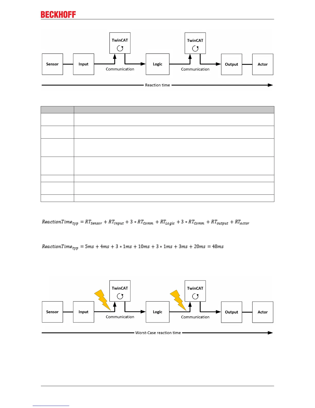
Fig.27: Typical reaction time
Definition Description
RTSensor Reaction time of the sensor until the signal is provided at the interface. Typically supplied by
the sensor manufacturer.
RTInput Reaction time of the safe input, such as EL1904 or EP1908. This time can be found in the
technical data. In the case of the EL1904 it is 4 ms.
RTComm Reaction time of the communication This is typically 3x the EtherCAT cycle time, because
new data can only be sent in a new Safety-over-EtherCAT telegram. These times depend
directly on the higher-level standard controller (cycle time of the PLC/NC).
RTLogic Reaction time of the logic terminal. This is the cycle time of the logic terminal and typically
ranges from 500 µs to 10 ms for the EL6900, depending on the size of the safety project.
The actual cycle time can be read from the terminal.
RTOutput Reaction time of the output terminal. This typically lies within the range of 2 to 3 ms.
RTActor Reaction time of the actuator. This information is typically supplied by the actuator
manufacturer
WDComm Watchdog time of the communication
This results in the following equation for the typical reaction time:
with, for example
Worst-case reaction time
The worst case reaction time is the maximum time required to switch off the actuator in the case of an error.
Fig.28: Worst-case reaction time

 Loading...


