Product overview, digital output terminals
EL20xx, EL2124 25Version: 5.2
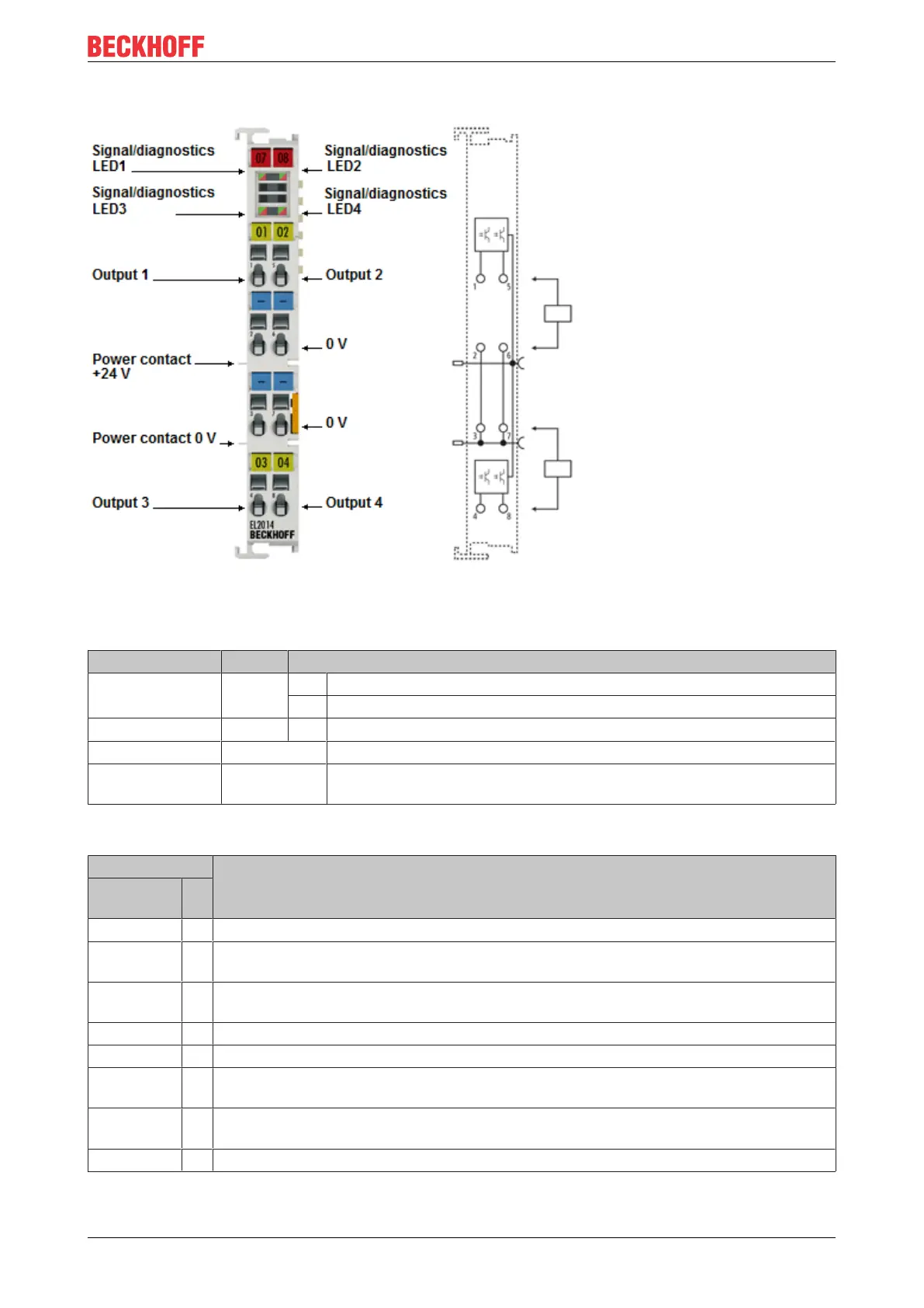
2.2.3 EL2014 - LEDs and pin assignment
Fig.18: EL2014
EL2014 - LEDs
LED Color Meaning
OUTPUT 1- 4 green off No output signal
on Output signal 24V
OUTPUT 1- 4 red on ERROR: Overcurrent / Overtemperature
Flashing red ERROR: Short circuit to 24V
OUTPUT 1- 4 red / green
alternating
ERROR: Open Load
EL2014 - Pin assignment
Terminal point Description
Designa-
tion
No.
Output 1 1 Output 1
0V 2 Ground for output1 (internally connected to terminal point3, 6, 7 and negative power
contact)
0V 3 Ground for output3 (internally connected to terminal point2, 6, 7 and negative power
contact)
Output 3 4 Output 3
Output 2 5 Output 2
0V 6 Ground for output2 (internally connected to terminal point2, 3, 7 and negative power
contact)
0V 7 Ground for output4 (internally connected to terminal point2, 3, 6 and negative power
contact)
Output 4 8 Output 4