Product overview, digital output terminals
EL20xx, EL212460 Version: 5.2
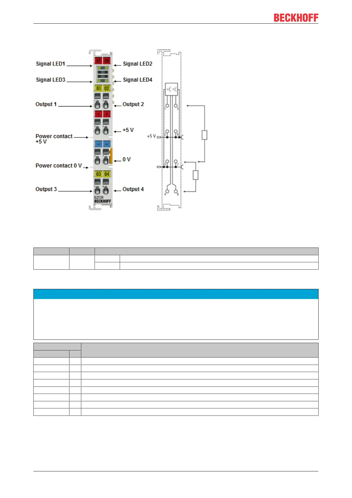
2.7.2 EL2124 - LEDs and connection
Fig.41: EL2124
LEDs
LED Color Meaning
OUTPUT 1- 4 green off No output signal
on 5 V
DC
output signal at the respective output
EL2124 - Connection
NOTE
5 V DC at the power contacts
During configuration of the Bus Terminal block, please note that the power contacts of the EL2124 carry a
voltage of 5 V
DC
(provided e.g. by an EL9505 power supply terminal).
If 24V terminals are to operate in the terminal block simultaneously, measures must be implemented for
electrical isolation (e.g. through the EL9190 power feed terminal or the EL9080 separation terminal).
Terminal point Description
Name No.
Output 1 1 Output 1
+5V 2 +5V (internally connected to terminal point6 and positive power contact)
0V 3 0V (internally connected to terminal point 7 and negative power contact)
Output 3 4 Output 3
Output 2 5 Output 2
+5V 6 +5V (internally connected to terminal point2 and positive power contact)
0V 7 0V (internally connected to terminal point 3 and negative power contact)
Output 4 8 Output 4