Commissioning
EL500x114 Version: 3.6
5.4 EL5001, EL5002
5.4.1 Function principles and notes
The EL5001/EL5002 is an SSI master terminal for cyclic polling of SSI devices. The EL5002 can operate two
slaves.
The EL500x is generally operated such that each I/O cycle triggers an SSI communication and thus supplies
a new encoder position to the application. If the time falls below a minimum EtherCAT cycle time that
depends on the settings and the hardware, this interrelationship can no longer be guaranteed and the SSI
transfers are no longer synchronous to the EtherCAT cycle and the DC cycle (see below: EtherCAT cycle
time).
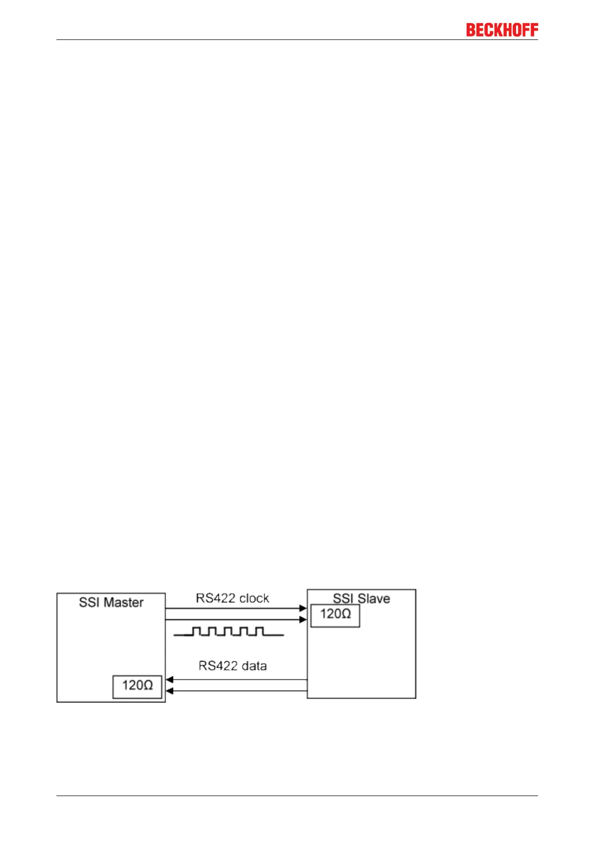
SSI principles
SSI communication sequence
• The SSI master starts pulsing on the clock line with a fixed cycle into the shift register of the SSI slave.
• The slave generally "pushes back" data with a width of 25bits on the data line. An SSI encoder should
determine its position with the first falling edge of the signal at the Clock input ("latching"), which is then
transferred.
• Once the specified number of bits was pushed, the clock signal is terminated.
• After a pause, polling by the SSI master recommences.
The last data bit can be a PowerFail bit, i.e. the slave signals a power failure. This output depends on the
slave.
The number of bit changes equals the clock frequency, i.e. the maximum data transfer rate for a 1MHz cycle
is 1Mbit/s.
The EL500x devices have a 120Ω termination resistor in the incoming data line.
Various parameters have to be set in the EL500x SSI master in order to ensure that the data of the SSI slave
are transferred correctly:
• Baud rate (e.g. 500 kBaud)
• Coding (e.g. Gray code)
• Data frame type, e.g. multi-turn 25 bits
• Data frame size, e.g. 25bits
• Data length, i.e. how many bits in the data frame represent the actual position data, e.g. 24 bits.
This information can be found in the data sheet for the SSI slave and must be set in the CoE directory of the
EL500x.
Fig.139: Schematic diagram
 Loading...