Mounting and wiring
EL500x46 Version: 3.6
4.10.2 EL5002
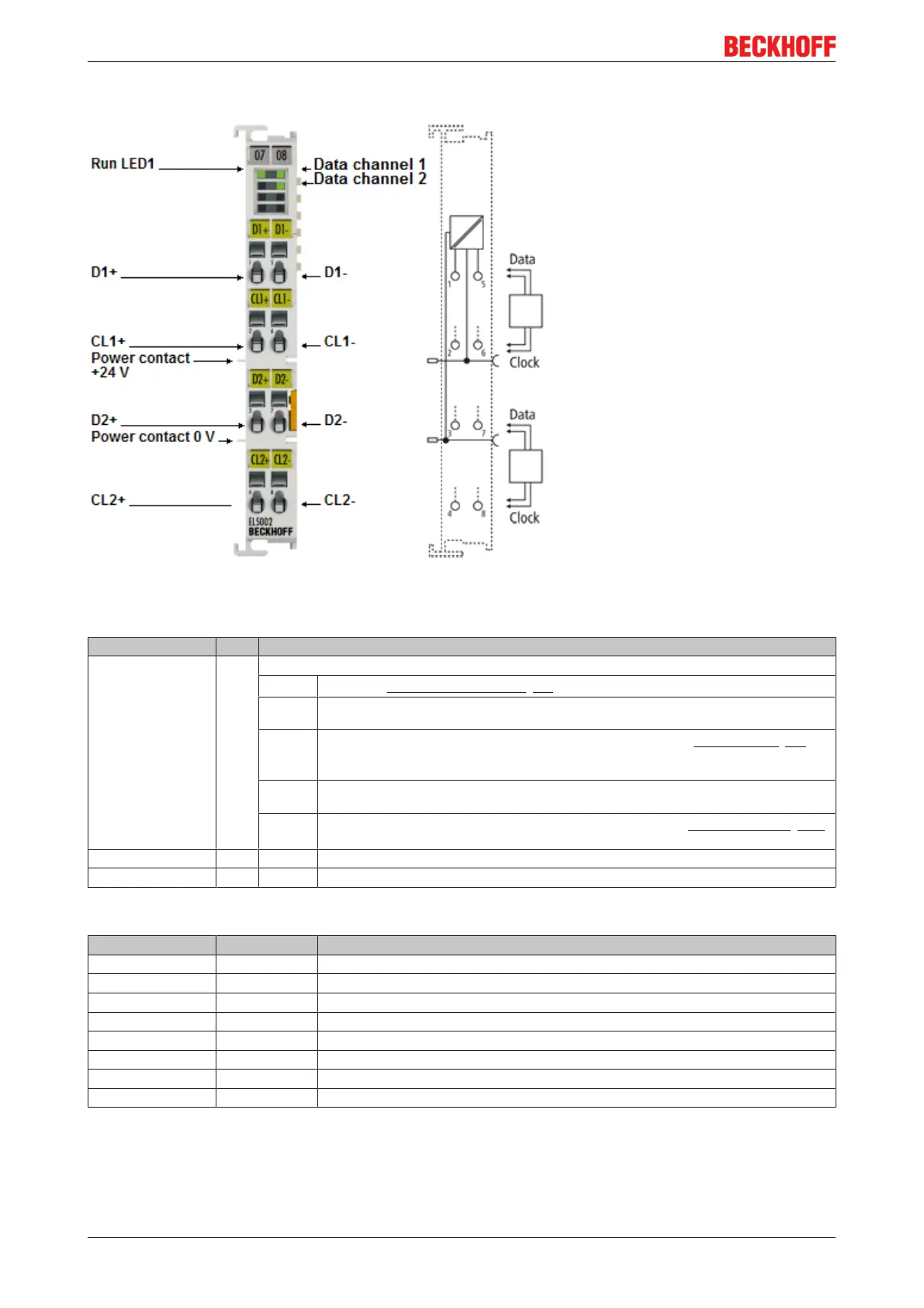
Fig.32: LEDs and connection EL5002
LEDs
LED Color Meaning
RUN green These LEDs indicate the terminal's operating state:
off
State of the EtherCAT State Machine [}97]: INIT=initialization of the terminal
flashing State of the EtherCAT State Machine: PREOP = function for mailbox communication and dif-
ferent standard-settings set
single
flash
State of the EtherCAT State Machine: SAFEOP = verification of the Sync Manager [}98]
channels and the distributed clocks.
Outputs remain in safe state
on State of the EtherCAT State Machine: OP = normal operating state; mailbox and process
data communication is possible
flickering
State of the EtherCAT State Machine: BOOTSTRAP = function for firmware updates [}155]
of the terminal
Data channel 1 green on Data is received from the encoder on channel 1.
Data channel 2 green on Data is received from the encoder on channel 2.
Connection
Terminal point No. Comment
D1+ 1 SSI data input D1+
CL1+ 2 Clock output CL1+
D2+ 3 SSI data input D2+
CL2+ 4 Clock output CL2+
D1- 5 SSI data input D1-
CL1- 6 Clock output CL1-
D2- 7 SSI data input D2-
CL2- 8 Clock output CL2-
 Loading...