4
INSTALLATION
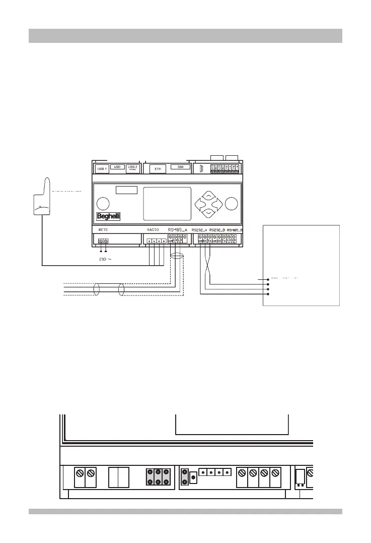
Use the layout below for reference to connect the Logica FM Control Unit to the Logica FM radio
circuit and to the optional DIN printer (RS232 bus).
The connection with the system, using the Logica Visual or the SD Manager software, can be
established through different channels:
- RS485-A;
- Ethernet;
- Modem 4G LTE integrato;
- Wifi
OkEsc
O
UTPUT
I
NPUT
A
ntenna
G
SM
60425
L
OGICA FM CONTROL UNIT
CODE 21102
RADIO CIRCUIT
LOGICA FM
CODE 1213
D
IN PRINTER
CODE - 3284
DTR (YELLOW)
TX (BLUE)
RX (GREY)
GND (BLACK)
USE AND TERMINATION OF RS 485 LINES
The control unit is equipped with 2 independent RS 485 lines (RS485_A and RS485_B) both
with adaptation of the line impedance by inserting 2 riders at 2.54 pitch.
Line adaptation is necessary when the control unit is located as a "terminal" element of BUS
485 (start or end of the route).
To adapt the RS485_A line, insert the Jumper in connectors J22 and J23
To adapt the RS485_B line, insert the Jumper in connectors J20 and J21
COM
UX
-
UX
+
RETE
RADIO
P
N
RS485_A
OUT3
+
-
5V IN
Reset
BOOT
00 - SD
01 - eMMC
10 - NAND
Term. 485
J20
J21
J23
J22