7
MIDI FOOT CONTROLLER FCB1010
1.3 Control elements
1.3.1 Front panel
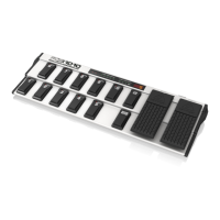
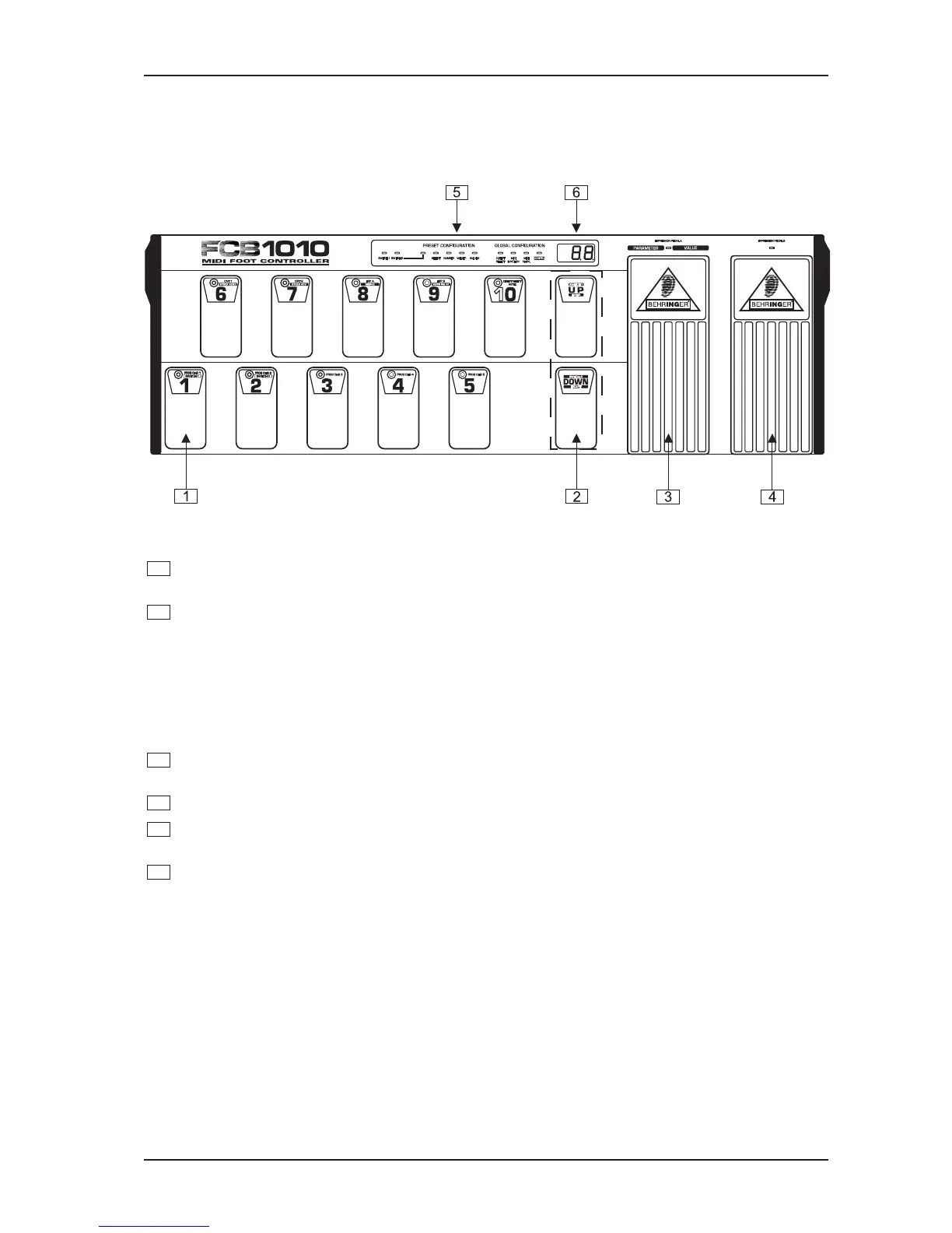
Fig. 1.1: Front panel control elements
1
The foot switches 1 through 10/0 allow you to select PRESETS, program your FCB1010 and enter
data in programming mode.
2
The UP/DOWN switches are used to scroll through the various BANKS and programming levels. In
programming mode, UP and DOWN are your ENTER and ESCAPE keys respectively.
+ When DIRECT SELECT mode is activated (see chapter 2 PROGRAMMING THE FCB1010), the
UP/DOWN switches are no longer needed for BANK selection and are free to perform a special
function: in the GLOBAL SETUP menu you can program them to control the SWITCH RELAYS
(UP: SWITCH 1 RELAY, DOWN: SWITCH 2 RELAY). In this case, you can toggle between the
preprogrammed SWITCH settings, each time you step on these switches.
3
EXPRESSION PEDAL A. Allows you to change controller values continuously. In programming mode,
the pedal is used for data entry.
4
EXPRESSION PEDAL B. Allows you to change controller values continuously.
5
STATUS-LEDs. The yellow LEDs display the current status of the PRESET programming or GLOBAL
SETUP functions.
6
LED-Display. Informs you about the currently selected BANK/PRESET number. In programming mode,
it displays any value changes.
1. INTRODUCTION