32 MODEL D User Manual
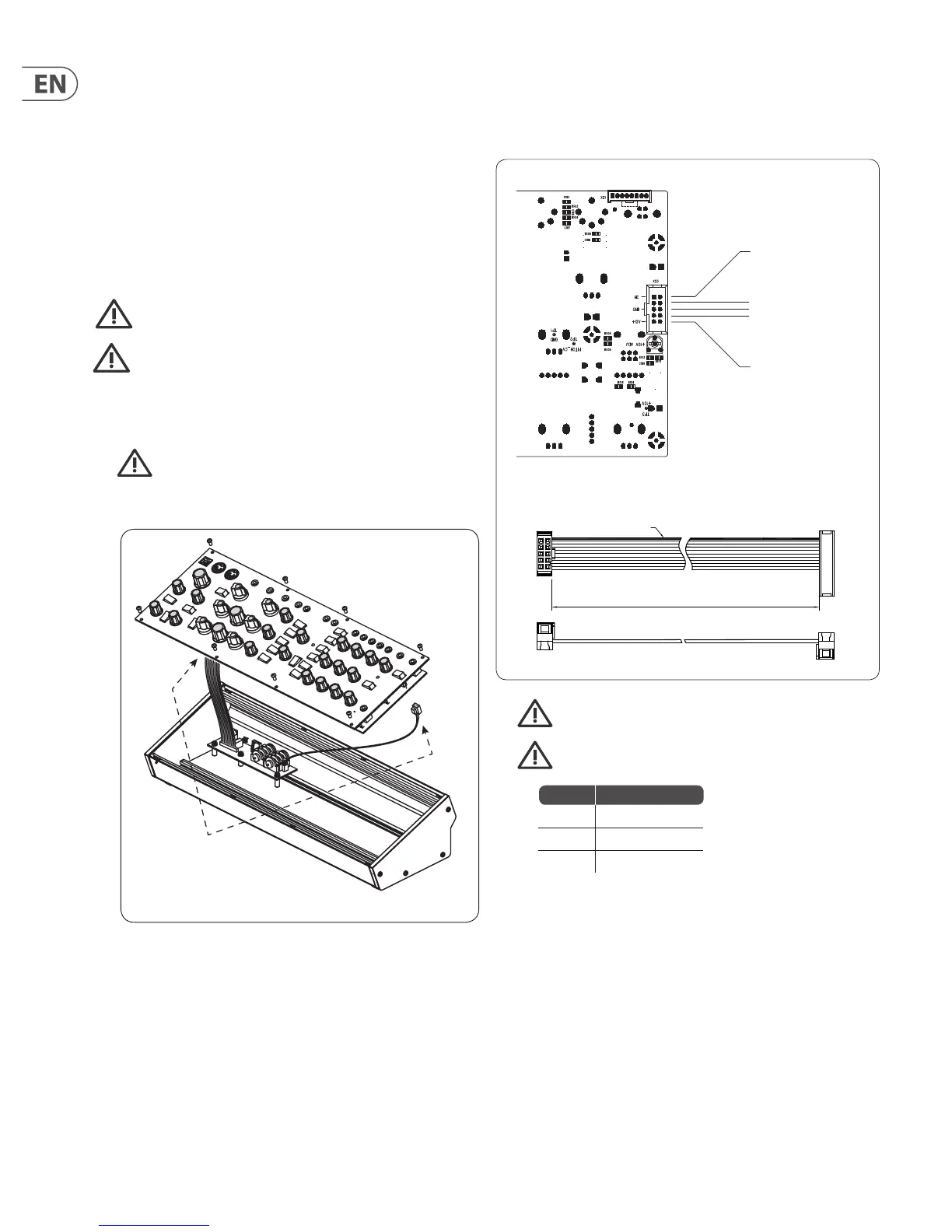
5. Securely connect the 10-pin end P1 of the supplied adapter cable to
connector X23 on the Main PCB of the MODEL D.
6. Make sure your power supply is turned o and disconnected from
the AC mains.
7. Make sure that your power supply will supply the following to the
pins of connector X23, as shown in the diagram above.
8. Securely connect the 16-pin end P2 of the supplied adapter cable to your
power supply, and double check all connections are correct.
9. Securely install the MODEL D Synthesizer into your Eurorack, using 8 screws
in the front panel.
10. Perform a full test and safety test before using the MODEL D.
11. The 3.5 mm MAIN OUT connector on the top panel is used instead of the ¼"
rear outputs which are no longer present.
400 mm ± 10
12
910
1
15
2
16
Red Stripe
Supplied Eurorack Power Supply Cable, Part # A74-0001-79446
Connect End P1 to Connector X23 on main PCB
Pins 1 and 2
No Connection
X23
X21 No Connection
Pins 3 to 8
Ground
Pins 9 and 10
+12 VDC
P1 P2
Pins Connection
1 and 2 No Connection
3 to 8 Ground
9 and 10 +12 VDC
8. Eurorack Installation
The MODEL D synthesizer can be removed from its factory chassis and installed
into a standard Eurorack chassis (not supplied). The module width is 70HP.
We recommend that this procedure is undertaken only by an experienced service
technician, to prevent personal injury, or damage to the unit.
The Eurorack case will need its own suitable power supply unit to power the
MODEL D synthesizer.
A 10-pin connector on the rear of the main PCB of the MODEL D allows the +12
VDC power supply connection to be made. A 10-pin to 16-pin adapter ribbon
cable is supplied to connect to your power supply.
Before proceeding, make sure that your power supply is capable of
supplying +12 VDC, 1 Amp.
Make sure that the connections using the supplied adapter cable will
supply the ground and power to the correct pins of X23.
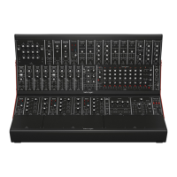
8.1 Procedure
Follow all steps in the order in which they are presented.
1. Disconnect the power cord and all other connections to the
MODEL D.
2. Undo the 8 screws on the top panel as shown. There is no need to undo any
other screws.
3. Disconnect the two cables from the lower side of the main PCB of the
MODEL D, and remove the assembly from the chassis.
4. Store the chassis assembly and the power supply adaptor in a dry safe place.