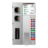
GN-9289 User Manual
Page 3 of (70)
G-series GN-9289 Modbus TCP_UDP Rev. 1.01.docx
Contents
1.
Important Notes .............................................................................................................................................. 6
1.1.
Safety Instruction ............................................................................................................................................ 7
1.1.1
Symbols ............................................................................................................................................... 7
1.1.2
Safety Notes ......................................................................................................................................... 7
2.
Specification ................................................................................................................................................... 8
2.1.1 GN-9289 (MODBUS TCP) ......................................................................................................................... 8
2.2.
General Specification ...................................................................................................................................... 9
2.2.1
General Specification .......................................................................................................................... 9
2.2.2 Interface Specification ...................................................................................................................... 10
2.3. GN-9289 LED Indicator ................................................................................................................................. 11
2.3.1
Module Status LED (MOD) ................................................................................................................ 11
2.3.2
Physical Connection LED(LINK) ...................................................................................................... 11
2.3.3
Exchange Data/Traffic Present LED(ACTIVE) ................................................................................. 12
2.3.5
Field Power Status LED .................................................................................................................... 12
3.
Dimension ..................................................................................................................................................... 13
3.1 GN-9289 ........................................................................................................................................................... 13
4.
Mechanical Set Up ........................................................................................................................................ 14
4.1 Total Expansion ............................................................................................................................................... 14
4.2. Plugging and Removal of the Components. ................................................................................................ 14
4.3 Module mounting .......................................................................................................................................... 15
4.4
How to supply the power correctly ............................................................................................................. 16
5.
Convenience Function .................................................................................................................................. 17
5.1.
Web Server .................................................................................................................................................... 17
5.2 IAP Functionality ............................................................................................................................................. 19
6.
GN-9289 Communication Interface ............................................................................................................. 21
6.1 RJ-45 Socket ................................................................................................................................................. 21
6.2 Dip Switch (TBD)........................................................................................................................................... 21
6.3 RS232 Port for MODBUS/RTU, Touch Panel or IOGuide ........................................................................... 22
6.4. MODBUS/TCP IP – Address Setup ............................................................................................................ 23
6.4.1
IP-Address Setup using BOOTP/DHCP Sever ................................................................................. 23
6.4.2
IP-Address Setup using DIP switch (Manual function) .................................................................. 24
7.
I/O Process Image Map ................................................................................................................................ 28
7.1.
MODBUS Interface Register/Bit Map ........................................................................................................... 29