22
Recharge the Vehicle A/C System
Thechargingprocessdiffersfromvehicletovehicle.
Chargefunctionforvehiclesequippedwithasingle-
servicettingshouldbecarriedoutmanually.Referto
thevehicleservicemanualforspecicinstructions.
Automaticleaktestswillbeperformed.Toavoidfalse
failures,thetemperaturesofthevehiclesystemandthe
recoverymachineshouldbewithin±5degreesC.
1.Connectbothservicehosestothevehicle’sservice
portsandturnthequickcouplersclockwise.
2.PressCHARGE.(Chargemodeafterinjectingoil
allowsonlyahigh-sidecharge.)Thedisplayshows
Operating Instructions — Charge
HP
LP
HP + LP
UV Dye
Oil (2)
Oil
Refrigerant
1
2
3
6
4
5
7
3.RefertovehicleA/Csystemspecicationsto
determinewhichservicehose(s)tochargethrough.
Usethenumberkeys1–3onthekeypadtoenter
thatspecication.Forselections4–7,enteravalue
andpressOK.
4.PressOKtolockinthevaluesandbeginthecharge
process.Movingorbumpingthemachineatthis
pointmayresultinaninaccuratecharge.When
thechargecyclegetsclosetothedesiredweight
value,themachineslowsdown.Itwillcharge,settle,
chargeagain,settle,etc.
5.Closethecouplervalves.Whenprompted,remove
servicehosesfromtheA/Csystem,andinstallthe
hosesonmachine’sstorageports.
6.PressOKtobeginclearinghosestopreparethe
machineforthenextservice.Whenhosesareclear,
thedisplayshowsasummaryofchargeresults,
whichcanbeprintedout.
ThevehicleA/Csystemisnowreadyforuse.
WARNING: To prevent personal
injury while working with refrigerant,
read and follow the instructions
and warnings in this manual, and
wear protective equipment such as
goggles and gloves.
CAUTION: If the low-side (blue) or high-
side (red) coupler valve is left open
during the hose clearing process, the
system will pull refrigerant back out of
the vehicle.
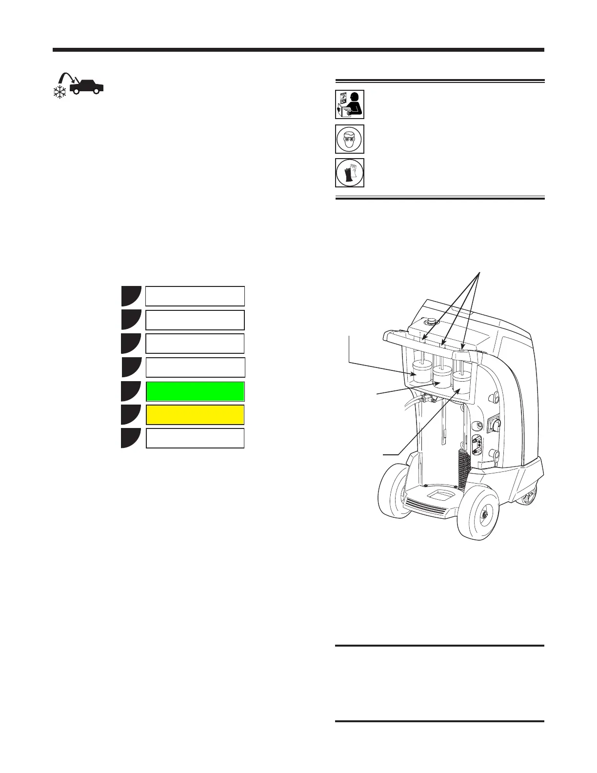
Figure 10
Oil Inject
Bottle 2
(greencolor
oncover)
Oil Inject
Bottle 1
(whitecover)
UV Dye
Inject Bottle
(yellowcolor
oncover)
Magnetic Couplers


 To Next Page