BelAir20E User Guide System Overview
April 2, 2012 Confidential Page 5 of 255
Document Number BDTM02201-A01 Standard
Hardware
Description
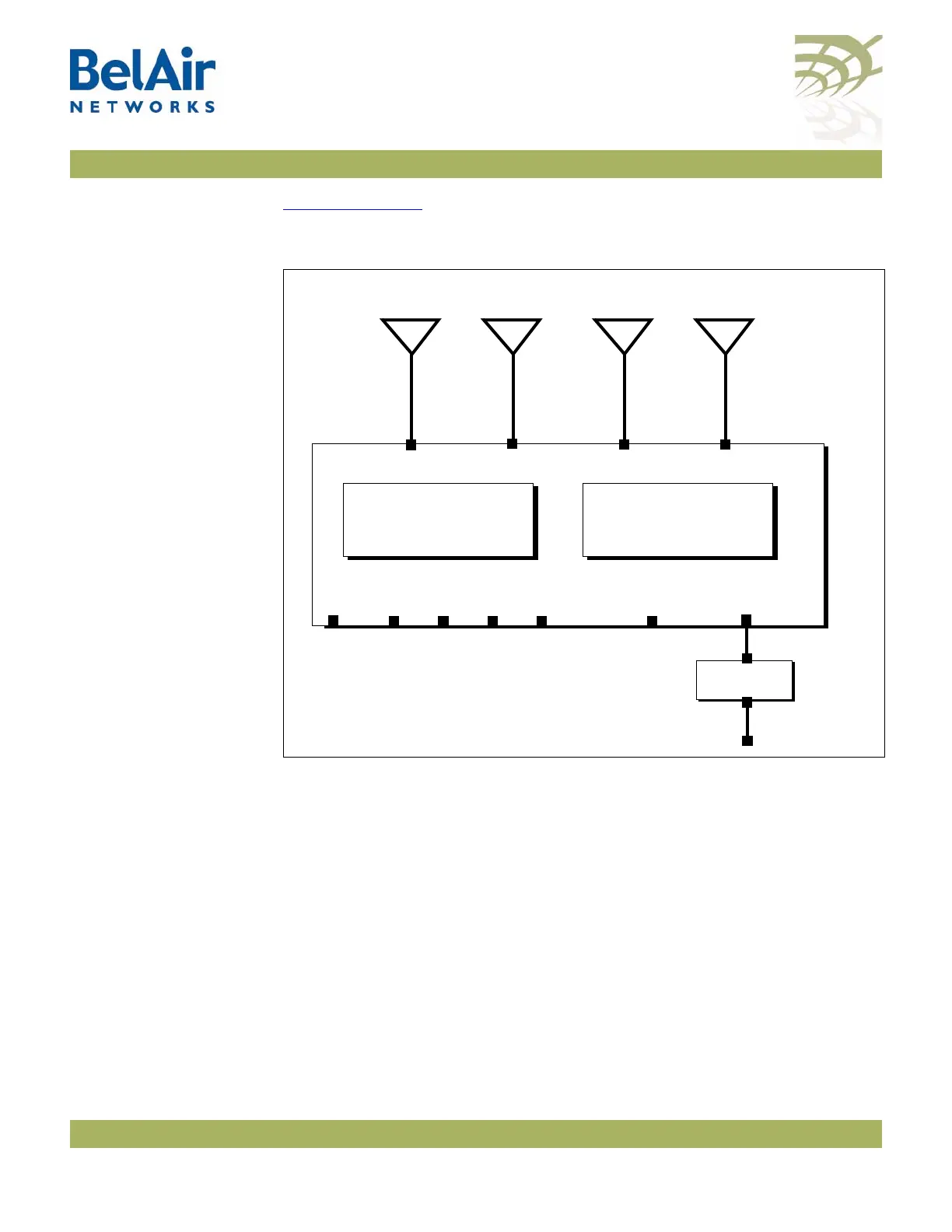
Figure 1 on page 5 shows the relationship between the main BelAir20E
hardware modules.
Figure 1: BelAir20E Hardware Module Block Diagram
The BelAir20E consists of the following modules:
• one High Throughput Module Evolved (HTME) providing:
—a wireline 10/100/1000 Base-TX WAN Ethernet interface to the Internet
—four wireline 10/100/1000 Base-TX LAN Ethernet interfaces
—a 2.4 GHz Wi-Fi radio and a 5.8 GHz Wi-Fi radio (-11 model only) using
fully compliant 802.11n links. Each radio can act as an Access Point (AP)
or provide backhaul links. An AP provides user traffic wireless access to
the BelAir20E. Backhaul links connect to other BelAir radios to create a
radio mesh.
• four integrated dual-band antennas (-11 model only)
• an external connector field
HTME
5.8 GHz
Radio
AC Power
Adapter
Antenna 0
LAN
48 V DC
Antenna 1 Antenna 2
2.4 GHz
Radio
100-240 V AC
Reset
Antenna 3
WAN
PoE
LAN LAN LAN
-11 model only
-11 model only
-11 model only