Service Manual iFLEX2 with iSCOUT expert compact
18 50 650 69 0101E_REV D (GROVE RT-TM).DOC / Rev. D / 2015-11-20 / JPD
9 LOAD SENSING
Please note that the load displayed by the LMI is not a direct measurement, but a calculated value
that is based on a lot of factors. Outside of the measured values (sensors), those include:
Operator settings such as:
o Operating mode/configuration
o Parts of Line/Reeving
Rigging parts such as:
Hookblock weight
Sling weights, etc.
Tip height (length of load line used)
Boom weights
Boom attachments such as
Stowed jibs
Auxiliary boom nose, etc.
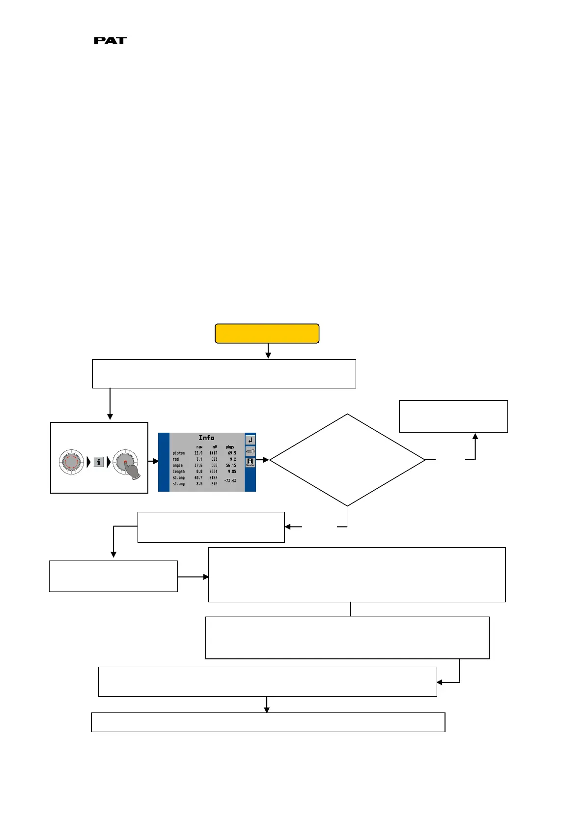
9.1 LOAD SENSING ERROR - FLOW CHART
First, verify the slew angle displayed through the console
by using the sensor output screen.
Slew potentiometer is
functioning correctly.
Does the
displayed value
differ from the
actual value?
The slew unit output can be found on pins 8 and 9. In order to
measrure current, however, you must disconnect a pin and
measure in line (between the cable from the slew unit and the
central unit). *The two outputs will vary as shown in chart below.
Ensure that the slew pot unit
is supplied with crane voltage.
Pin 7 must carry crane
voltage and Pin 2 is GND.
You can also leave the wires connected as use your meter in
Voltage-mode to measure the output signals. In this case,
you will see the 4…20mA range as a 1.1 to 5.5 Volt range.
If the voltage or currents do not fall in line with the charts and tables shown
below, and no system errors are present, the problem may be mechanical.
Open the slip ring unit and determine if the slew potentiometer is set correctly.