Service Manual iFLEX2 with iSCOUT expert compact (Grove RT-TM)
© 2015 HIRSCHMANN Automation and Control GmbH 7
3.3 DESCRIPTION OF THE SYSTEM COMPONENTS
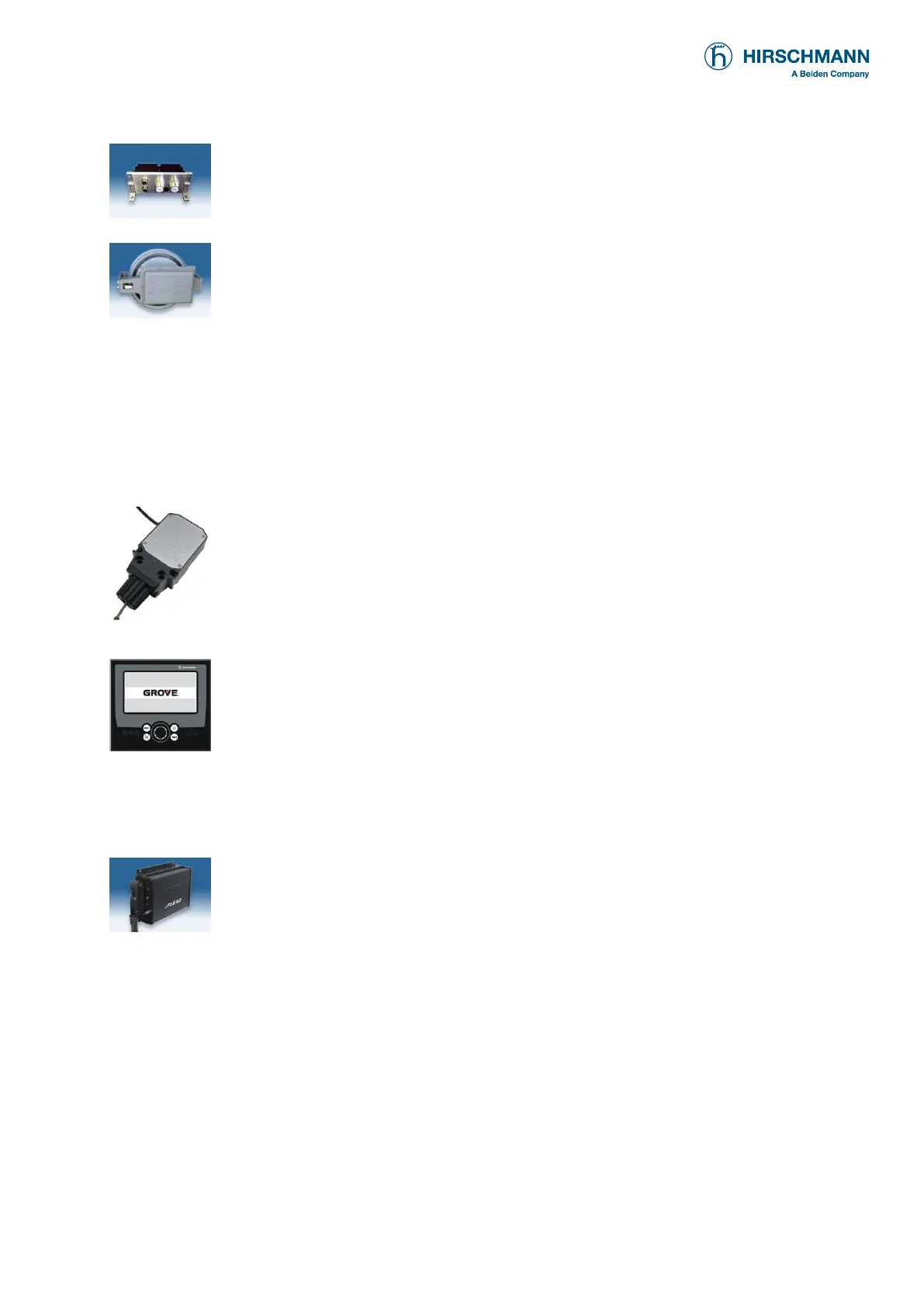
Pressure Transducer: The pressure transducer converts hydraulic pressure into
an electric signal. A pressure transducer block houses two transducers, CAN bus
converter board, and two bus connectors. One pressure transducer is connected
to the piston side of the lift cylinder and the other to the rod side.
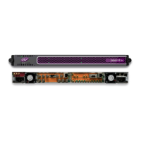
The Length-Angle Transducer: The length-angle sensor (LWG), often referred
to as the “cable reel”, is a combination of two transducers in one box, installed on
the base section of the boom. It measures the length and the angle of the boom.
A reeling drum drives a potentiometer, which is the length transducer. Part of the
length transducer circuit is the length cable on the drum, which is a multi-
conductor cable. It is connected to the anti-two-block switch at the boom head
and to a slip ring body in the LWG.
The angle transducer is a potentiometer driven by a weighted pendulum that is oil
damped. Both length and angle transducer are connected to a CAN bus controller
board, which is connected to the bus system.
Anti-Two-Block Switch: The anti-two-block switch monitors the load block and
it’s relationship with the head of the boom. In working condition the switch is
closed. When the load block strikes the weight the circuit opens, disengaging a
relay output to the lock out solenoid valves, where applicable. To check the cable
for damage, (short circuit to ground) there is a 4.7k resistor between ground and
the contact of the switch, to give a signal back to the central unit. The weight at
the anti-two-block switch keeps the switch closed until the load block strikes it.
Console: The graphic console displays all geometrical information such as length
and angle of main boom, working radius and head height of the boom. It also
displays the actual load and the maximum load permitted by load chart.
Furthermore, it has an alarm horn, a warning light for overload, and a pre-warning
light. The graphic display allows for a simple interactive configuration setup, as
well as sensor calibration (zero adjustment), and troubleshooting sensor output
screen. The console has a warning light for anti-two-block conditions and an
override switch for overload or anti-block condition.
Refer to Operator’s Handbook for detailed operation of the console.
Central Unit: Inside the central unit there is a CPU. The central unit has a hard
mounted connector for all signals. A status indicator (7-segment display) shows
operation and error codes.
Slew Potentiometer: This component is not supplied by PAT/Hirschmann. It is
part of the electrical swivel (slip ring assembly). The potentiometer has two
wipers which are used to determine the slewing angle (rotational positioning) of
the super structure in relation to the carrier. The slew input to the central unit is
not a CAN signal, but rather two 4..20mA analog signals.