FIGURE 3
[3a] INSTALLATION OF WK TYPE
When mounting MODEL 096 arm bracket, the wall and the strength of the hardware used must be
checked and veried as being adequate to withstand a 45 kg shear load and 200 kg withdrawal force
at each of the three mounting bolts. When using concealed wiring, a ush mounted junction box
with the necessary conduit and wiring must be pre-installed at 113 cm from the oor.
1. ARM MOUNTING BRACKET (FIGURE 2):
1-1. Remove bottom cover from bottom of the arm mounting
bracket. Snake electrical interconnecting wires through brack-
et and out access hole.
1-2. Using ø 9 X 75 mm bolts in top and lower mounting holes,
mount arm mounting bracket on wall.
DO NOT FULLY
TIGHTEN
.
1-3. Placing a level across top edge of arm mounting bracket,
level bracket then tighten bolts securely.
1-4. Put the bolt cap to each head of bolt.
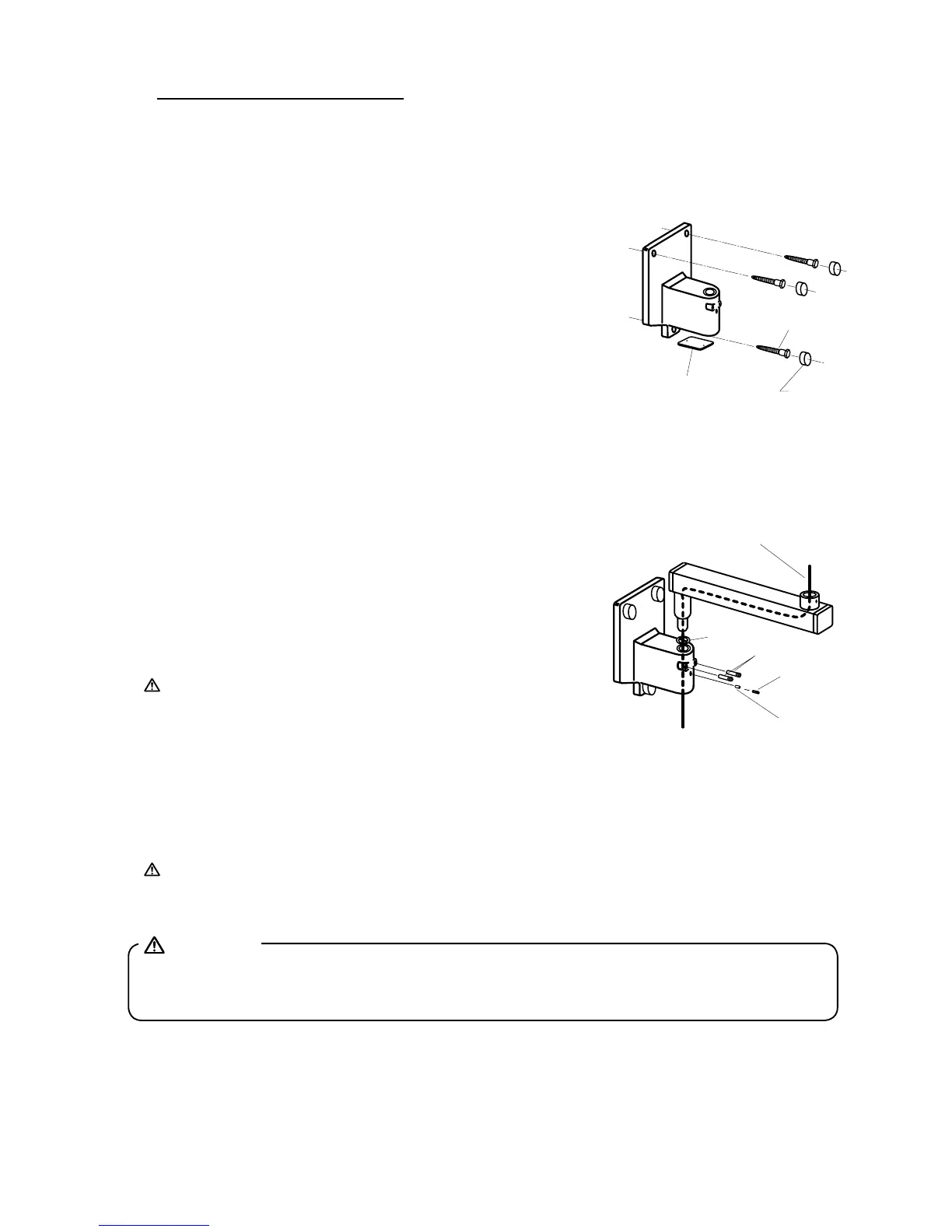
2. HORIZONTAL ARM (FIGURE 3):
2-1. Cut pull string on horizontal arm. DO NOT REMOVE STRING.
ALLOW ONE END TO EXTEND BEYOND MALE BARB AND THE OTHER END TO EX
-
TEND BEYOND THE FEMALE MOUNT.
2-2. Place a thrust washer over the hole of arm mounting
bracket, and insert male barb into arm mounting bracket,
allowing pull string to extend through access opening on
bottom of the arm mounting bracket.
2-3. Insert two retaining bolts securely into upper threaded
holes of arm mounting bracket and tighten securely.
IMPORTANT:
The retaining bolts must securely engage
the annular groove of horizontal arm. The removal of the
retaining bolts will allow the horizontal arm to rise verti-
cally, and out of, the arm mounting bracket.
2-4. Insert brake plug then brake screw (M6x6 mm) into the
lower threaded hole of the arm mounting bracket.
DO NOT FULLY TIGHTEN
.
2-5. Place a level on the horizontal arm and conrm that the arm is level in its left and right swing
positions.
NOTE:
Final leveling of horizontal arm is described on Page 19.
3. BALANCE ARM ASSEMBLY (FIGURE 4):
WARNING:
DO NOT RELEASE ARM HOLDING BAND UNTIL THE X-RAY HEAD HAS BEEN INSTALLED.
BALANCE ARM ASSEMBLY IS SPRING LOADED AND CAN CAUSE EQUIPMENT DAMAGE AND
INJURY IF NOT HANDLED IN THE PROPER MANNER.
3-1. DO NOT REMOVE ARM HOLDING BAND.
3-2. Secure pull string to cable and pulling the opposite end, snake cable through horizontal arm and
arm mounting bracket.
3-3. Insert brake plug then brake screw (M 6 X 6 mm) into the horizontal arm collar.
DO NOT FULLY TIGHTEN
.