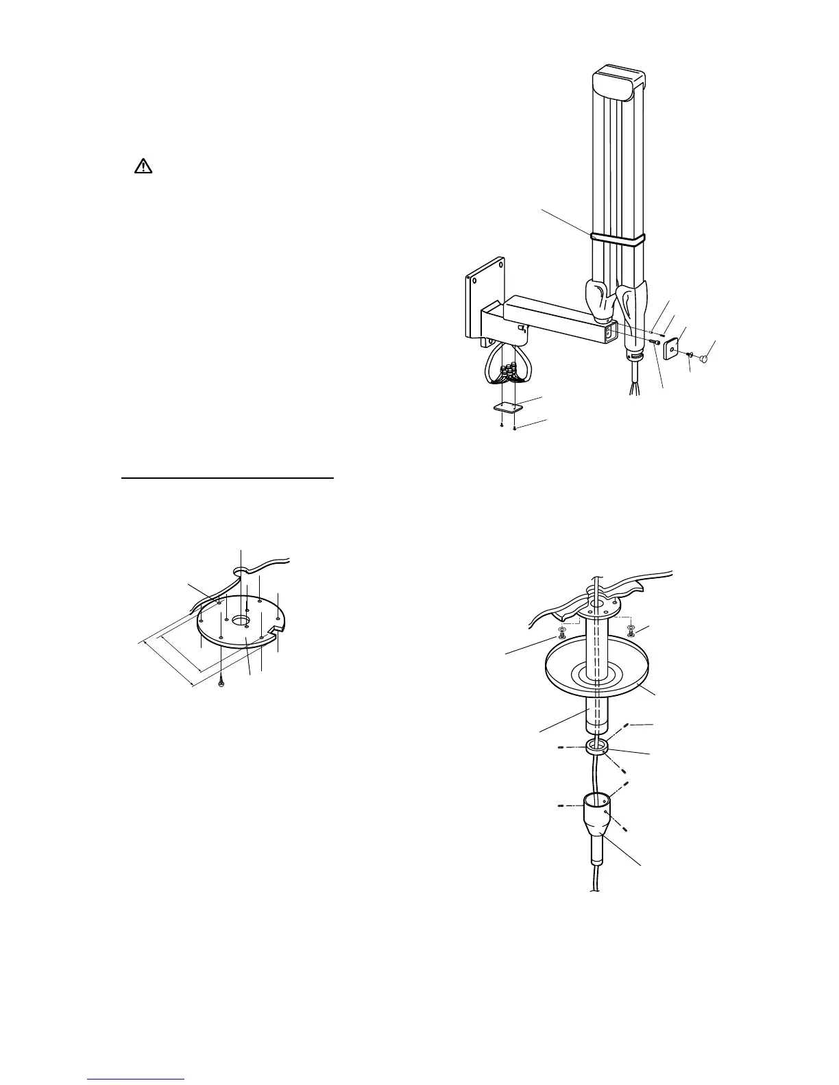
3-4. Remove end cap screw and open end cap.
3-5. Insert stopper screw into upper threaded hole inside
horizontal arm and tighten securely.
CAUTION:
If stopper screw is not tightened
securely, the scissors arm can move vertically up
and out of the horizontal arm
3-6. Cut cable and interconnecting wires to a workable
length. Strip 10mm of wire insulation from each lead.
With wire crimping pliers use supplied wire nuts
to make wire connections.
3-7. Insert connected wires into the arm mounting
bracket and secure the bottom cover to the bottom
of the arm mounting bracket.
3-8. Secure end cap with end cap screw, and place a
screw cover.
FIGURE 4
[3b] INSTALLATION OF CK TYPE
1. Fix the mounting plate to the ceiling. Make sure the mounting plate is rmly xed and can with-
stand a 150 kg (330 pound) withdrawal force. (FIGURE 5)
FIGURE 5
From 2004 July
FIGURE 6
2. Attach the pole to the mounting plate by three mounting
bolts. Make the pole vertical by adjusting three adjust-
ment bolts and three mounting bolts. (FIGURE 6)
3. Set the cover and cover ring to the pole and tighten the set
screws of cover ring as the cover stays at the upper end of
the pole. (FIGURE 6)
4. Attach the swing post to the bottom end of the pole.