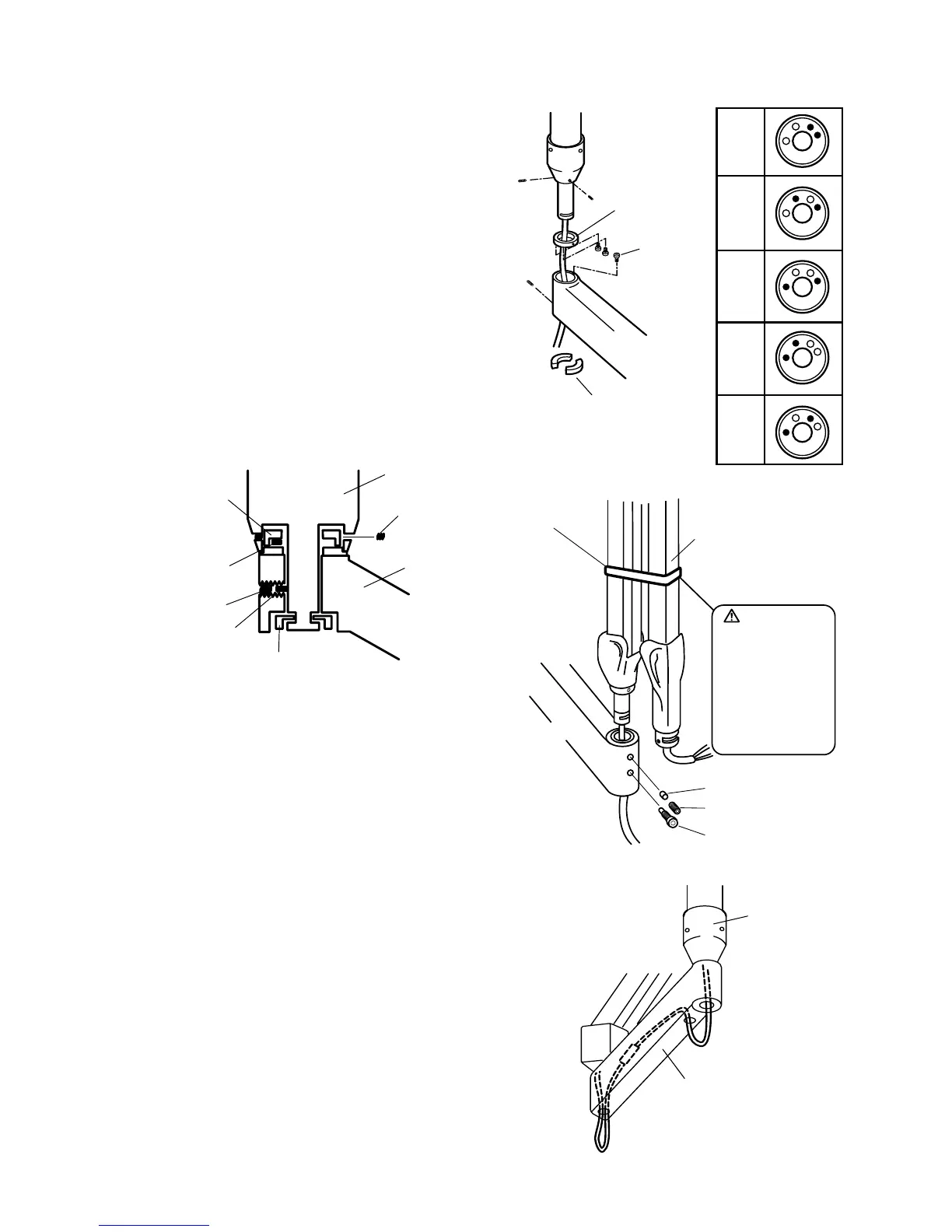
5. According to the desired rotation angle of swing
arm, set the stopper screw to the stopper ring. 9
different angles can be obtained by changing the
position of stop screws. Right table shows the re-
lation between the rotation angle of swing arm and
the position of stopper screws. (FIGURE 7)
6. Set the stopper ring, swing arm and keys to the
swing post. After the swing arm is lowered to the
limit, make sure the stopper ring is in contact with
the swing arm. (FIGURE 7)
7. Fix the stopper ring to the swing post by the set
screws. Start position of the rotation of swing arm
is decided by these set screws. (FIGURE 8)
FIGURE 8
8. Insert the shaft of balance arm to the swing arm.
Set a brake plug then brake screw into the top
threaded hole of the swing arm. Do not fully tight-
en. Set a stopper screw into lower threaded hole
of swing arm and tighten securely. (FIGURE 9)
9. Connect the cables from the balance arm and the
cables from the control box under the pole. Then
put the cables into the swing arm. (FIGURE 10)
10. Refer to page 16 for Head assembly installation.
11. Refer to page 17 for Control box installation.
12. Perform the post installation inspection.(page 19~20).