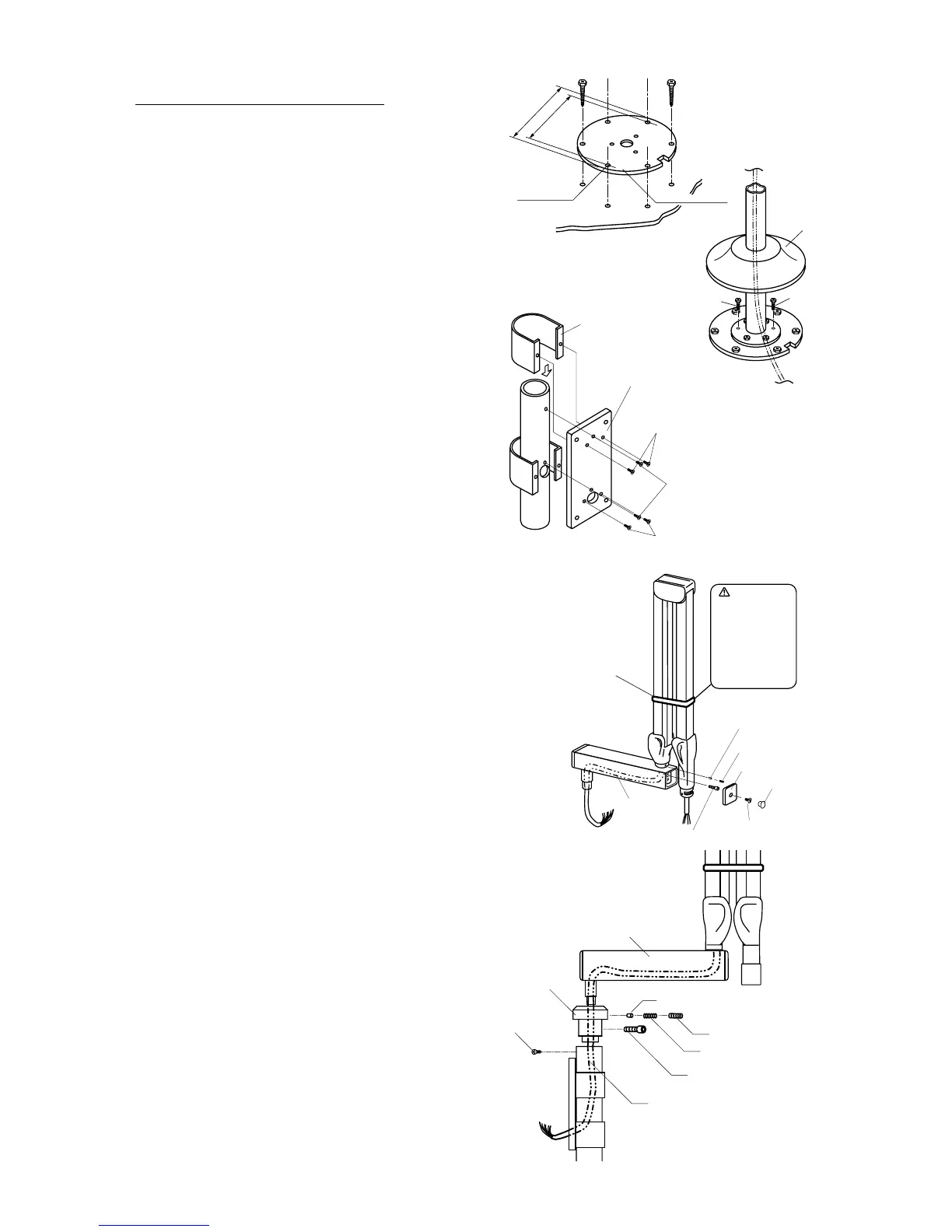
[3c] INSTALLATION OF FK1 TYPE
1. Fix the mounting plate to the floor. Make sure the
mounting plate is firmly fixed and can withstand a
150kg(330 pound) withdrawal force.(FIGURE 11)
2. Attach the pole to the mounting plate by three mount-
ing bolts. Make the pole vertical by adjusting three
adjustment bolts and three mounting bolts. Then set
the cover to the pole. (FIGURE 12)
3. Set the control box mounting plate to the pole by two
mounting plate screws, then slide the back supporter
of mounting plate and x two back supporter screws
from the control box mounting plate.(FIGURE 13)
4. Through the cable from balance arm to the horizontal
arm, then Joint balance arm and horizontal arm by
stopper screw, brake plug and brake screw. (FIG-
URE 14)
5. Insert the pole busing into the shaft of horizontal arm.
Set stopper screw, brake plug, brake spring and brake
screw. (FIGURE 15)
6. Insert the pole bushing into the pole as the wires go
through the access hole of control box mounting
plate. (FIGURE 15)
7. Then adjust swing range of the arm and x the two
mounting screws for pole busing. Conrm the swing
range of arm is as physical dimension.(Page 5)
8. Refer to page 16 for Head assembly installation.
9. Refer to page 17 for Control box installation.
FIGURE 13
FIGURE 12